 Facebook
 Google
 GitHub
 Linkedin
Hi all,
I have two different separate circuits, both consumer doorbells, with momentary switches to trigger the bell. I have been trying to find a way to link the two circuits so that one momentary switch will trigger the other, but also keeps the circuits separate (so that nothing breaks). Essentially I would like to turn these two separate switches into a DPST switch.
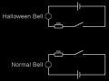
The circuit that I want to act as the trigger is a novelty halloween doorbell, supplied with 4.5V. The other circuit that is to be triggered is my normal wireless doorbell with its own momentary switch which runs on 3V. I've modeled these two circuits as per the attached image. The wireless (normal) doorbell is small and the board fits inside the halloween doorbell; as such space is limited. Preferably I'd like to use the components I have on hand which are various resistors, diodes, and MOSFETs (npn and pnp).
Can anybody point me in the right direction?
I have two different separate circuits, both consumer doorbells, with momentary switches to trigger the bell. I have been trying to find a way to link the two circuits so that one momentary switch will trigger the other, but also keeps the circuits separate (so that nothing breaks). Essentially I would like to turn these two separate switches into a DPST switch.
The circuit that I want to act as the trigger is a novelty halloween doorbell, supplied with 4.5V. The other circuit that is to be triggered is my normal wireless doorbell with its own momentary switch which runs on 3V. I've modeled these two circuits as per the attached image. The wireless (normal) doorbell is small and the board fits inside the halloween doorbell; as such space is limited. Preferably I'd like to use the components I have on hand which are various resistors, diodes, and MOSFETs (npn and pnp).
Can anybody point me in the right direction?
Attachments
-
 16.9 KB Views: 16


