Facebook
 Google
 GitHub
 Linkedin
Hi!
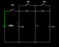
Im trying to build the circuit in the attached image. But i cant figure out how i would replace the switches with MOSFETS so that i can controll them with my arduino uno.
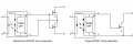
I have some N-channel MOSFETS (IRF7010PbF) laying around which is hope to use. But maybe i need some other components to make this work.
ive been thinking about using opto-couplers to isolate the arduino. But still i cant figure out how to connect everything to the arduino.
Below is a description of the system:
1: S1 turns on to charge the first capacitor.
2: S1 turns off.
3: S2 turns on. current goes though the inductor.
4: S2 turns off. Back EMF is collected in the second capacitor.
5: S3 turns on. current goes though the inductor in the opposite direction.
6: S3 turns off. Back EMF is collected in the first capacitor.
And here is a link to my attempt in the falstad.com simulator. The inductive load seam to interfere with the MOSFET's or maybe its the simulator that isn't accurate? http://tinyurl.com/y35yp7r4
Im trying to build the circuit in the attached image. But i cant figure out how i would replace the switches with MOSFETS so that i can controll them with my arduino uno.
I have some N-channel MOSFETS (IRF7010PbF) laying around which is hope to use. But maybe i need some other components to make this work.
ive been thinking about using opto-couplers to isolate the arduino. But still i cant figure out how to connect everything to the arduino.
Below is a description of the system:
1: S1 turns on to charge the first capacitor.
2: S1 turns off.
3: S2 turns on. current goes though the inductor.
4: S2 turns off. Back EMF is collected in the second capacitor.
5: S3 turns on. current goes though the inductor in the opposite direction.
6: S3 turns off. Back EMF is collected in the first capacitor.
And here is a link to my attempt in the falstad.com simulator. The inductive load seam to interfere with the MOSFET's or maybe its the simulator that isn't accurate? http://tinyurl.com/y35yp7r4
Attachments
-
 10.7 KB Views: 23
Last edited by a moderator: