Using a negative trigger to trip multiple relays - little different take.

Thread Starter

fastboarder

Joined May 17, 2023
13
Hi folks,
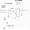
I have seen a number "like" threads but of course every one is nuanced. I cooked up a circuit diagram which I am confident needs a bit of scrutiny and seeing if you could provide any feedback on improvements or no-no's (or ridicule for that matter).
I am using a puddle circuit from a 2016 4Runner to trip multiple relays. I believe do not believe there is enough amperage (3A) to use safely hence the multiple relays. The SSR is from another person which was a great idea to sever any feedback which might get to the ECU which would be a sad day for my wallet. I use the output of a negatively triggered circuit to create a positive output of relay 2 which can then be used to trip the relays which will be delivering power to the accessories.
I am unclear if this would work correctly or if there is a better way to accomplish this task. Also, the diode values I am not clear on based I am not sure what the resistive specs would be or what amperage might try to swim upstream.
Any input you have would be appreciated!Rock Light and Interior Ideal Circuit T.jpg
 

sghioto

Joined Dec 31, 2017
5,380
Don't see the need for one relay to turn on a second relay if my interpretation is correct.
This is how I see the circuit operating if the 4Runner white wire is a negative trigger.
The trigger operates the relay which turns on both the Rock and Cargo lights.
I'm also assuming the Auxbeam is separately controlling those lights even though your schematic only shows one wire through diodes to both.
1684425967930.png
 
Last edited:

panic mode

Joined Oct 10, 2011
2,715
the first problem is that components are not annotated. each one should have label (CR1, CR2, D1,D2, ...) so that one can comment on it. either way, circuits in posts 1 and 2 it will do nothing since there is no way for SSR to turn on the relays CR1 and CR2 due lack of 12V supply at the SSR. the last one by ghioto, using single relay does better job. this one can work. 1N5404 are rateed for up to 3A but relay contact of an automotive relay should handle way more so single relay is fine.
 

Thread Starter

fastboarder

Joined May 17, 2023
13
relay.jpgThanks for marking up my drawing, appreciate the input, first one I have done. For the SSR, the trigger and 12V is coming from the vehicle as the light circuit is activated. Once it latches (negative) it will pass the trigger to the second mosfet. I want the SSR as a trigger only to the second relay where it will open 12V from a fused source to power the accessory circuit. The cap in the circuit keeps a steady voltage to stop any relay chatter caused by PWM of the dimming light circuit in the vehicle. For the SSR so I do need it.
 

sghioto

Joined Dec 31, 2017
5,380
So this photo of the circuit, is that working the way you want it? Do you just need to show that correctly in a schematic?
 

Thread Starter

fastboarder

Joined May 17, 2023
13
I guess this forum auto closes an edit as I timed out. So in my drawing, the ground is needed on the input to the SSR, the white puddle wire I noted is likely the 12V positive as this is the wire the power will be applied from the vehicle, which is a negative trigger. So the question I have then which kind of makes sense is the SSRs usually ues an optocoupler correct? So in no manner would it pass any voltage/current from the input side? The picture I just posted which doesn't help much from a circuit diagram standpoint allegedly works according to the SSR portion of my drawing. I say allegedly as now that you've pointed this out, unless the power is being supplied by the vehicle input side of the SSR, I do not see where else power would be coming from on the output to power a trigger.
 
Last edited:

Thread Starter

fastboarder

Joined May 17, 2023
13
Don't see the need for one relay to turn on a second relay if my interpretation is correct.
This is how I see the circuit operating if the 4Runner white wire is a negative trigger.
The trigger operates the relay which turns on both the Rock and Cargo lights.
I'm also assuming the Auxbeam is separately controlling those lights even though your schematic only shows one wire through diodes to both.
View attachment 294466
Yes, all your points are correct - thank you!!!
 

djsfantasi

Joined Apr 11, 2010
9,156
@sghioto ’s schematic corrects an error in your posted schematic. There is no way the second relay (circled in yellow below) would ever activate as there is no way power can be applied to its coil. The NO contact prevents this. This is regardless of if the COM terminal could ever receive +12V.
IMG_4890.jpeg
 

Thread Starter

fastboarder

Joined May 17, 2023
13
So this photo of the circuit, is that working the way you want it? Do you just need to show that correctly in a schematic?
Great question. Sorry, for the ADHD posts, when I went to reply, I had come back and was signed out before I had time to finish my reply. The picture of the SSR and Relay in the project box supposedly works. It works according to my initial drawing as it was the original I based my idea off of. I've attached the original here.
Pin 87 in this use case is getting the voltage/amps from the vehicle. The 12V he shows as part of the manual switch as another trigger does not provide any power to the circuit unless the manual switch is used. The person who made this original I believe has no 12V fused power to the SSR, had as I thought the lines which cross the the 12V manual input show an insulated wire cross , only using the power from the vehicle on what I am guess is the white wire. Wish this had audio chat because I am really screwing up writing down an explanation. Appreciate your patience.
 

Attachments

Last edited:

djsfantasi

Joined Apr 11, 2010
9,156
Great question. Sorry, for the ADHD posts, when I went to reply, I had come back and was signed out before I had time to finish my reply. The picture of the SSR and Relay in the project box supposedly works. It works according to my initial drawing as it was the original I based my idea off of. I've attached the original here. View attachment 294494
Pin 87 in this use case is getting the voltage/amps from the vehicle. The 12V he shows as part of the manual switch as another trigger does not provide any power to the circuit unless the manual switch is used. The person who made this original has not 12V fused power, only using the power from the vehicle on what I am guess is the white wire. Wish this had audio chat because I am really screwing up writing down an explanation. Appreciate your patience.
The “bump and line” method of drawing schematics hasn’t been used in a while. This schematic isn’t clear to me if the four wires in the circled area below are connected.
IMG_4891.jpeg
 

Thread Starter

fastboarder

Joined May 17, 2023
13
The “bump and line” method of drawing schematics hasn’t been used in a while. This schematic isn’t clear to me if the four wires in the circled area below are connected.
View attachment 294496
Until this was pointed out the SSR would not be have any power passing through it, my question is the same as yours. I was unclear as well and assumed they were not connected. I believe from yours and sghioto's input likely this is supposed to be connected or in my case as sghioto corrected is to have the 12V fused power into pin 1 of the SSR.
 

Thread Starter

fastboarder

Joined May 17, 2023
13
I think the 12V pin 1 solution is very helpful. I guess my only question now is the capacitor best placed on the SSR between pins 2 and 4 as you can see in the picture and diagram? As the PWM dims the circuit and the voltage slowly decreases on the white wire, this causes the mechanical relay to chatter. I see you removed that in your circuit sghioto but is it okay to do this way?
 

sghioto

Joined Dec 31, 2017
5,380
I would have placed the cap C1 across the input side of the SSR with an isolation diode D1.
Should be able to use a much smaller cap.
Add D2 to suppress the reverse EMF from the relay when it shuts OFF.
1684446846825.png
 

Thread Starter

fastboarder

Joined May 17, 2023
13
Very cool, any chance you can add this to the corrected drawing you did with the second relay? I was literally using paint...So I can place the cap on the SSR like the actual pic, instead of pins 2 to 4, put it on pins 3&4 with the diode placed on the white puddle wire going to the SSR pin 3? For the cap I was going to use a 25V 680uF cap. Would this work or what value would you suggest?
 

Thread Starter

fastboarder

Joined May 17, 2023
13
Are you speaking of the schematic in post #2?
I also use paint to copy and paste schematics.
Try using a 47uf cap.
Yes, the one in post 2. I will be using post 2 with a cap on 3 and 4 as you suggested. Perfect, will pick up some of those caps. Thank you!
 
Top