Using MOSFET to convert PWM- to PWM+ (and Failing)

Thread Starter

middie51

Joined Sep 12, 2024
11
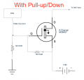
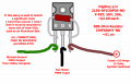
Apologies for being a total circuit noob, I'm trying to invert a low side PWM signal to a high side PWM signal, and I came across a thread elsewhere on this forum where @LowQCab explained how to do this a P channel MOSFET and a resistor, which I soldered up, and It does not seem to being doing what I need.

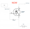
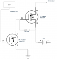
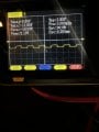
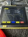
The circuit is wired up as shown in his original diagram (attached). When everything is connected, with a multimeter, it's showing the perfect frequency is measured (1khz, just as on the input), but the duty cycle is just pegged at 100% no matter how I vary it on the input (connected to the gate). Any suggestions as to what's going on? Is the source voltage too high (and thus needs a voltage divider)? It's 12v (this is an automotive application).

The parts I used for this are:
MOSFET - ‎IXTH50P10‎
Resistor - CMF55500R00FEBF‎

I really appreciate any help!
 

Attachments

LowQCab

Joined Nov 6, 2012
5,101
How have You determined whether You have a Switched-Ground, or a Switched-Hot that needs to be inverted ?

Any Schematics or Pictures could possibly explain a lot, and eliminate some confusion.

You probably have a Switched-Hot, which will NOT work with the Circuit I provided earlier,
but, some semi-good news, most likely the FET that You need is
a "N-Channel" FET which will likely be cheaper to purchase than a "P-Channel" FET.

How much Current does your "Automotive-application" draw ?
Controlling a Cooling-Fan, or AC-Blower, or large aftermarket-Fuel-Pump, is not a trivial task.
.
.
.
 

Thread Starter

middie51

Joined Sep 12, 2024
11
How have You determined whether You have a Switched-Ground, or a Switched-Hot that needs to be inverted ?

Any Schematics or Pictures could possibly explain a lot, and eliminate some confusion.

You probably have a Switched-Hot, which will NOT work with the Circuit I provided earlier,
but, some semi-good news, most likely the FET that You need is
a "N-Channel" FET which will likely be cheaper to purchase than a "P-Channel" FET.

How much Current does your "Automotive-application" draw ?
Controlling a Cooling-Fan, or AC-Blower, or large aftermarket-Fuel-Pump, is not a trivial task.
.
.
.
Thanks for responding! It's almost the same application as that original thread, it's an output from the same ECU that person was using (A Holley Terminator X) and it's specified as PWM-. I would imagine it should be very low current, it's only a 22ga wire from the ECU, and it's intended to control small sensor devices and such.

This output will basically only be controlling a DAC. It's a LARGE fuel pump (5.0 GPM), but this is not part of the power circuit for the pump, it's just the speed controller. The DAC is made for a similar application, and it will convert a PWM+ to a 0-5v analog output (which will then go to the pump controller), but it doesn't work with a PWM-, hence this intermediate step.

I've tested the controller with a generated analog signal, and I've used a PWM+ signal generator to send to the DAC, and then to the pump controller, and it varied the speed exactly as it should. So, if I can get PWM+ TO the DAC, it should work.
 

Thread Starter

middie51

Joined Sep 12, 2024
11
That doesn't sound right. Are you measuring it connected to the mosfet?
What is generating this pwm signal?
It's an engine control unit ... this is measured before the MOSFET, it's exactly what's coming out of the ECU. It's a switched ground that generates the pulse. The way I understood PWM- is that it's switching between ground and open as the two states to generate the digital signal.
 

sghioto

Joined Dec 31, 2017
8,633
Connect it back up to the mosfet circuit and measure the pwm voltage at the gate as shown below.
I'm also concerned about that 500 ohm resistor. The value might be too low.
1726704989762.png
 
Last edited:

LowQCab

Joined Nov 6, 2012
5,101
The Holley-Computer should have all of it's PWM Outputs operating as Switched Grounds,
and those PWM-Outputs should be fine up to about ~3-Amps or so of Current,
so a ~500-Ohm Pull-Up-Resistor should be a very light Load for it.
This is virtually a standard specification for all aftermarket ECUs,
but this needs to be verified as I haven't personally worked on a Holley-System.

This Output Specification should be plainly spelled-out in the Holley PDF.
Please post the Holley-Operators-PDF.

To test the Circuit that I provided, simply Ground the Gate-Pin while measuring the Voltage at the Drain-Pin.
The Voltage should go to a full ~12-Volts as long as the Gate-Pin is Grounded.
There is virtually "no-Load" on the Drain-Pin when the FET is "Off".
in this condition, the Drain-Pin is considered to be "Floating", ( not connected to anything ).

Your DMM Meter may give almost any random indication on a "Floating" Drain-Pin.

You can not accurately measure a PWM-Output with an ordinary Digital-Multi-Meter.
For truly meaningful measurements, an Oscilloscope is required.
Handheld 'Scopes are available, but they can be of limited use sometimes, with their teeny-tiny screens.

It may be that your DAC needs a "Pull-Down" Resistor,
another ~500-Ohm Resistor can do this job if there is no Pull-Down-Resistor already on the DAC-Input.
If the Input of the DAC is left in a "floating" condition,
it is very likely that the DAC will do "something" completely unpredictable.

.
.
.
 

Thread Starter

middie51

Joined Sep 12, 2024
11
The Holley-Computer should have all of it's PWM Outputs operating as Switched Grounds,
and those PWM-Outputs should be fine up to about ~3-Amps or so of Current,
so a ~500-Ohm Pull-Up-Resistor should be a very light Load for it.
This is virtually a standard specification for all aftermarket ECUs,
but this needs to be verified as I haven't personally worked on a Holley-System.

This Output Specification should be plainly spelled-out in the Holley PDF.
Please post the Holley-Operators-PDF.

To test the Circuit that I provided, simply Ground the Gate-Pin while measuring the Voltage at the Drain-Pin.
The Voltage should go to a full ~12-Volts as long as the Gate-Pin is Grounded.
There is virtually "no-Load" on the Drain-Pin when the FET is "Off".
in this condition, the Drain-Pin is considered to be "Floating", ( not connected to anything ).

Your DMM Meter may give almost any random indication on a "Floating" Drain-Pin.

You can not accurately measure a PWM-Output with an ordinary Digital-Multi-Meter.
For truly meaningful measurements, an Oscilloscope is required.
Handheld 'Scopes are available, but they can be of limited use sometimes, with their teeny-tiny screens.

It may be that your DAC needs a "Pull-Down" Resistor,
another ~500-Ohm Resistor can do this job if there is no Pull-Down-Resistor already on the DAC-Input.
If the Input of the DAC is left in a "floating" condition,
it is very likely that the DAC will do "something" completely unpredictable.

.
.
.
Hey, I want to say thanks again for the help figuring this out, it's greatly appreciated! Do you think trying a pull-up or pull-down on this is worth a shot? I understand the concepts, but I'm still wrapping my head around it. Unfortunately Holley is really not with it when it comes to documentation ... I'm going to call them for more clarification. However, what IS in the manuals says 2amps is the max. The following is all that's in there:

All PWM (Pulse Width Modulated) and switched outputs are rated at a maximum of 2A. If a device will draw more than 2A, some type or relay must be used. If the output is PWM, do not use a “switching” relay, but rather a solid state type relay designed to be pulse width modulated.

1. “P-” – Ground Pulse Width Modulated output – Outputs a low side pulse width modulated output to control items such as a progressive nitrous solenoid or a PWM IAC. See above. Wiring: Connect the pin to the device to be triggered. A PWM device has 2 wires, connector the other side of the device to a voltage source.
 

LowQCab

Joined Nov 6, 2012
5,101
A ~500-Ohm Resistor, at ~14.5-Volts, = 15/500 = 0.030-Amps, or 30mA max..

A ~500-Ohm Resistor is "almost not there" as far as a "Load" on the Holley-PWM-Output goes,
it's just enough of a Load to insure suppression of unwanted "Electrical-Noise" getting into the wiring.

An additional 500-Ohm-Pull-Down-Resistor on the Input of your DAC
would be good insurance, and can't hurt anything.

.
.
.
 

Thread Starter

middie51

Joined Sep 12, 2024
11
A ~500-Ohm Resistor, at ~14.5-Volts, = 15/500 = 0.030-Amps, or 30mA max..

A ~500-Ohm Resistor is "almost not there" as far as a "Load" on the Holley-PWM-Output goes,
it's just enough of a Load to insure suppression of unwanted "Electrical-Noise" getting into the wiring.

An additional 500-Ohm-Pull-Down-Resistor on the Input of your DAC
would be good insurance, and can't hurt anything.

.
.
.

Ok, I'm trying to confirm what's inside the DAC, it's potted so I'll have to call them.

So, to try and un-stupefy myself, I made 2 diagrams, the first is what I have right now ... And the 2nd is what it sounds like is being suggested (minus the pull-down on the DAC). It seems like if I don't pull the gate to ground when the PWM is on, the whole thing might not work?
 

Attachments

LowQCab

Joined Nov 6, 2012
5,101
DO NOT put a Pull-Down-Resistor on a P-Channel-FET,
this will create a Voltage-Divider on the Gate of the FET,
which will cause it to only partially Switch, or possibly not Switch at all.
The P-Channel-FET already has the required "Pull-Up" Resistor installed.

DO INSTALL a Pull-Down-Resistor on the Input of your DAC.
To make sure that the Input of the DAC goes to Ground when the FET turns-Off
and the DAC-Input is possibly in a "floating" condition.

A 10K Resistor is not adequate for any position anywhere in this project, do not use it.
.
.
.
 
Last edited:

Thread Starter

middie51

Joined Sep 12, 2024
11
DO NOT put a Pull-Down-Resistor on a P-Channel-FET,
this will create a Voltage-Divider on the Gate of the FET,
which will cause it to only partially Switch, or possibly not Switch at all.
The P-Channel-FET already has the required "Pull-Up" Resistor installed.

DO INSTALL a Pull-Down-Resistor on the Input of your DAC.
To make sure that the Input of the DAC goes to Ground when the FET turns-Off
and the DAC-Input is possibly in a "floating" condition.

A 10K Resistor is not adequate for any position anywhere in this project, do not use it.
.
.
.
Ok, so I confirmed with the manufacturer that the DAC has an internal pull-down resistor, and I also tested the circuit as you suggested, and it checked out A-OK. So, would this be a better, albeit far less simple solution, with an N-channel MOSFET as a low side driver?

My brain wants to put a pull-down resistor on the gate of the N-Channel MOSFET, is that necessary?

Finally, when you say a 10k resistor is not adequate, is that because it would cause the gate to react too slowly for the application/limit current TOO much?
 

Attachments

LowQCab

Joined Nov 6, 2012
5,101
"" Ok, so I confirmed with the manufacturer that the DAC has an internal pull-down resistor, and I also tested the circuit as you suggested, and it checked out A-OK. So, would this be a better, albeit far less simple solution, with an N-channel MOSFET as a low side driver? ""
I don't understand what You are asking,
You just stated that the Circuit works,
so why would You want to complicate matters by trying to implement an N-Channel-FET ?
( and the proper term would be "Low-Side-Switch" )
------------------------------------------------------------------------------------------------------------------------

"" My brain wants to put a pull-down resistor on the gate of the N-Channel MOSFET, is that necessary? ""
( using an N-Channel-FET would just complicate matters, as above )

N-Channel-FETs ALWAYS get a Pull-Down-Resistor on the Gate.
P-Channel-FETs ALWAYS get a Pull-UP-Resistor on the Gate.
These rules always apply regardless of any other surrounding Circuitry.

A ~10K-Resistor will usually suffice for simple Gate-protection,
but in an extremely "Noisy" Electrical environment, such as a Car,
a much lower Impedance Resistor is a distinct advantage in reducing Electrical "Noise".

The Pull-Up/Down-Resistors are to insure that the Gates will NEVER be left in a "floating" condition,
( which could "potentially" damage, or even completely destroy, the FET ),
and that condition will be "Off", or "Open".
This also insures that the state of the FET is always predictable and
known when the Circuit is initially Powered-Up.

The Gate of a MOSFET-Transistor has an almost infinite Impedance and can
be turned-On or turned-Off, or even destroyed, by just looking at it the wrong way.

The Gate of a FET acts almost exactly like a Capacitor,
usually with a value between ~1nF and ~4nF, and a Voltage-Rating of less than ~20-Volts.
----------------------------------------------------------------------------------------------------------

"" Finally, when you say a 10k resistor is not adequate,
is that because it would cause the gate to react too slowly for the application/limit current TOO much? ""


This is "generally" correct.
A PWM Signal must usually be nice and square, either going vertical, or horizontal,
( this will depend upon its base Frequency ),
this would be simple, except for the fact that a FET's Gate acts like a Capacitor.

Now You have to find out how a simple "R/C" Filter works, and
how it will affect the "shape" of a Square-Wave such as a PWM-Signal

There is no such thing as a perfectly square, square-wave,
only one that is "square-enough" to reliably work in a particular Circuit.
------------------------------------------------------------------------------------------------------------

This is an exaggerated picture of what the PWM-Waveform would look like with a 10K-Resistor.

PWM Waveform .png
.
.
.
 
Last edited:

Thread Starter

middie51

Joined Sep 12, 2024
11
"" Ok, so I confirmed with the manufacturer that the DAC has an internal pull-down resistor, and I also tested the circuit as you suggested, and it checked out A-OK. So, would this be a better, albeit far less simple solution, with an N-channel MOSFET as a low side driver? ""
I don't understand what You are asking,
You just stated that the Circuit works,
so why would You want to complicate matters by trying to implement an N-Channel-FET ?
( and the proper term would be "Low-Side-Switch" )
------------------------------------------------------------------------------------------------------------------------

"" My brain wants to put a pull-down resistor on the gate of the N-Channel MOSFET, is that necessary? ""
( using an N-Channel-FET would just complicate matters, as above )

N-Channel-FETs ALWAYS get a Pull-Down-Resistor on the Gate.
P-Channel-FETs ALWAYS get a Pull-UP-Resistor on the Gate.
These rules always apply regardless of any other surrounding Circuitry.

A ~10K-Resistor will usually suffice for simple Gate-protection,
but in an extremely "Noisy" Electrical environment, such as a Car,
a much lower Impedance Resistor is a distinct advantage in reducing Electrical "Noise".

The Pull-Up/Down-Resistors are to insure that the Gates will NEVER be left in a "floating" condition,
( which could "potentially" damage, or even completely destroy, the FET ),
and that condition will be "Off", or "Open".
This also insures that the state of the FET is always predictable and
known when the Circuit is initially Powered-Up.

The Gate of a MOSFET-Transistor has an almost infinite Impedance and can
be turned-On or turned-Off, or even destroyed, by just looking at it the wrong way.

The Gate of a FET acts almost exactly like a Capacitor,
usually with a value between ~1nF and ~4nF, and a Voltage-Rating of less than ~20-Volts.
----------------------------------------------------------------------------------------------------------

"" Finally, when you say a 10k resistor is not adequate,
is that because it would cause the gate to react too slowly for the application/limit current TOO much? ""


This is "generally" correct.
A PWM Signal must usually be nice and square, either going vertical, or horizontal,
( this will depend upon its base Frequency ),
this would be simple, except for the fact that a FET's Gate acts like a Capacitor.

Now You have to find out how a simple "R/C" Filter works, and
how it will affect the "shape" of a Square-Wave such as a PWM-Signal

There is no such thing as a perfectly square, square-wave,
only one that is "square-enough" to reliably work in a particular Circuit.
------------------------------------------------------------------------------------------------------------

This is an exaggerated picture of what the PWM-Waveform would look like with a 10K-Resistor.

View attachment 332137
.
.
.
Ok, this makes sense, thanks for being patient with me. I've learned a TON in the last week trying to figure this out. I broke down and got my hands on a small oscilloscope, and you were right, it was enlightening. What the ECU is putting out (PWM- referenced off +12v) is attached below. The 2nd trace is the output I'm getting on the drain pin, referenced from ground, and it doesn't seem to be working for the DAC ...
 

Attachments

LowQCab

Joined Nov 6, 2012
5,101
Notice how the Waveform gradually tapers off to the right ?
That is a symptom of a charged-up Capacitor being gradually, slowly, discharged by a Resistor.
This would tend to indicate that a lower value Pull-Down-Resistor is needed.

Many Switching-Circuits, ( such as "maybe" your DAC ), do not play-nice with a slowly changing Waveform.
The Input wants to see a vertical-line, ( up and down ), preferably with very sharp corners.


The FET has a certain amount of Capacitance on it's Gate-Pin.
That Capacitance must be Charged-up, and then it must be Discharged,
preferably as fast as is practical.
This "appears" to be working just fine, according to your Scope-Pictures, ( guessing ).
Although, it's hard to tell exactly what's going on,
because the display is not adjusted to show "Ground" in the center of the display.

It is also possible that the Input to your DAC has a very small amount of Capacitance.
You stated that it has a Pull-Down-Resistor, what is it's value ?
A lower-Resistance-Resistor, ( such as maybe ~500-Ohms ), should work just fine to handle this job.
Please provide the Spec-Sheet-PDF for your DAC.

Please provide the current Schematic that
represents all of the components as they are currently connected during this test.

.
.
.
 
Last edited:

Thread Starter

middie51

Joined Sep 12, 2024
11
Notice how the Waveform gradually tapers off to the right ?
That is a symptom of a charged-up Capacitor being gradually, slowly, discharged by a Resistor.
This would tend to indicate that a lower value Pull-Down-Resistor is needed.

Many Switching-Circuits, ( such as "maybe" your DAC ), do not play-nice with a slowly changing Waveform.
The Input wants to see a vertical-line, ( up and down ), preferably with very sharp corners.


The FET has a certain amount of Capacitance on it's Gate-Pin.
That Capacitance must be Charged-up, and then it must be Discharged,
preferably as fast as is practical.
This "appears" to be working just fine, according to your Scope-Pictures, ( guessing ).
Although, it's hard to tell exactly what's going on,
because the display is not adjusted to show "Ground" in the center of the display.

It is also possible that the Input to your DAC has a very small amount of Capacitance.
You stated that it has a Pull-Down-Resistor, what is it's value ?
A lower-Resistance-Resistor, ( such as maybe ~500-Ohms ), should work just fine to handle this job.
Please provide the Spec-Sheet-PDF for your DAC.

Please provide the current Schematic that
represents all of the components as they are currently connected during this test.

.
.
.
Ok, I was unable to get a schematic from theand quite pricey) DAC was either faulty, or somehow not correct for the job. The pump speed now varies with duty cycle output on my 2D table as it should, and now I can configure it any way I want in software.

I did need to get a different MOSFET though:

Because of the saw-toothed output and your advice, on a hunch, certainly not know-how, I decided to try one with a much lower input capacitance, and low and behold I got a nice square wave output. The downside being the only ones that seemed suitable are a much smaller package, and a lot harder to work with. The first one I was using was roughly 4300 pF, and the one I have now is 60 pF, and that seems to have made the difference.

So my final question (I hope) is, any idea where to source a higher quality one of these DAC boards? It works pretty well, but it's clearly a very low grade component. If I can find a nicer one, I'd prefer to use that of course.
 
Last edited:

MisterBill2

Joined Jan 23, 2018
27,193
Certainly mosfet gate capacitance will slow things down and so prevent some wonderful ideas from becoming reality. It certainly makes driving them more complicated. Glad somebody was able to help solve the problem.
And just think about how much you learned!!
 
Top