Questions about my MOSFET switch using a 555 timer (latch on circuit)

Thread Starter

juliaaaan

Joined Jan 22, 2025
45
Hello everyone,
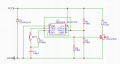
I have some questions about the electronic circuit I designed (see image). I don't have much experience with electronic circuits, so I'm posting here for help. The circuit is used to activate a heating element (for heated steering) using a push button and a latch-on circuit (based on a 555 timer) to switch on an n-channel MOSFET. Here are my questions about this circuit:

  • Value and wattage of gate resistor correct?
Value: I understand that it's possible to calculate the required theoretical value of this resistor, but I don't have all the necessary data for that calculation. Therefore, I made an estimate based on commonly chosen values found online and settled on 100Ω. I understand that this relatively high value might lead to a slower "on time," but since the MOSFET isn't switched rapidly, I thought this wouldn't be an issue, correct?

Wattage: I intend to use a 1210 SMD resistor with a power rating of ½ watt for this resistor. Will this be sufficient? This wattage will be briefly exceeded at the start when charging the capacitor in the MOSFET (W = (12 * 12) / 100 = 1.44), but because this is so brief, it shouldn't be a problem for the resistor, correct?


  • Heatsink required?
The MOSFET will need to handle a maximum of 4 amps. RDS(ON) is 7mΩ. So, the MOSFET will generate (4 * 4 * 0.007 =) 0.112 watts of heat. Is it correct that with such a low value, the MOSFET does not require a heatsink?


  • Electrolytic capacitor replacement with ceramic possible?
The 555 timer circuit is based on an article that designed several latch-on circuits. In this circuit, an electrolytic capacitor was used for C1 (see image). I'd like to use one or more ceramic capacitors due to space constraints. This seems fine to me, but I'd like confirmation.

Thank you in advance for your answers
 

Attachments

dl324

Joined Mar 30, 2015
18,219
Welcome to AAC!
  • Value and wattage of gate resistor correct?
Value: I understand that it's possible to calculate the required theoretical value of this resistor, but I don't have all the necessary data for that calculation. Therefore, I made an estimate based on commonly chosen values found online and settled on 100Ω.
R4 isn't required.
  • Heatsink required?
The MOSFET will need to handle a maximum of 4 amps. RDS(ON) is 7mΩ. So, the MOSFET will generate (4 * 4 * 0.007 =) 0.112 watts of heat. Is it correct that with such a low value, the MOSFET does not require a heatsink?
That seems to be the case. When MOSFETs are used as switches, and turned on sufficiently hard, power dissipation is low.
  • Electrolytic capacitor replacement with ceramic possible?
The 555 timer circuit is based on an article that designed several latch-on circuits. In this circuit, an electrolytic capacitor was used for C1 (see image). I'd like to use one or more ceramic capacitors due to space constraints. This seems fine to me, but I'd like confirmation.
A ceramic cap should be fine, but capacitance changes with temperature. An electrolytic capacitor will have more leakage current than ceramic.

I didn't check the wiring of the timer because pin function isn't labeled and a pin order symbol isn't very useful for conveying circuit intent.
 

crutschow

Joined Mar 14, 2008
38,316
Also C2 is not needed for that circuit.
It's only required if power line noise might affect timing accuracy when the 555 is used as a timer.

And C1 can be <1µF while still giving reliable switching, since it only has to generate a short pulse to switch the 555.
My simulation works down to 1nF so 100nF should be fine.
 

Thread Starter

juliaaaan

Joined Jan 22, 2025
45
Welcome to AAC!
R4 isn't required.
That seems to be the case. When MOSFETs are used as switches, and turned on sufficiently hard, power dissipation is low.
A ceramic cap should be fine, but capacitance changes with temperature. An electrolytic capacitor will have more leakage current than ceramic.

I didn't check the wiring of the timer because pin function isn't labeled and a pin order symbol isn't very useful for conveying circuit intent.
Thank you very much for your replay,I only have a question about R4.

What I understand about a gate resistor is that it prevents voltage spikes when turning the MOSFET on and off. Additionally, it limits high inrush current to protect the 555 timer (maximum output 225mA).

Do these rules not apply in this application?

P.S. The attachment shows the pinouts of the IC.
 

Attachments

dl324

Joined Mar 30, 2015
18,219
What I understand about a gate resistor is that it prevents voltage spikes when turning the MOSFET on and off. Additionally, it limits high inrush current to protect the 555 timer (maximum output 225mA).

Do these rules not apply in this application?
The voltage applied to the gate won't be higher than about 14V with the engine running. There can be higher voltage spikes on the battery so you might want a TVS diode on the timer circuit.

The timer should handle gate charging current without problems.
 

Thread Starter

juliaaaan

Joined Jan 22, 2025
45
The voltage applied to the gate won't be higher than about 14V with the engine running. There can be higher voltage spikes on the battery so you might want a TVS diode on the timer circuit.

The timer should handle gate charging current without problems.

The TVS diode indeed seems like a good idea, thank you. I do agree that the 555 IC will output a maximum of +/-14 volts. This is below the maximum gate voltage of 20 volts. However, I thought R4 was necessary to prevent voltage oscillation caused by the on/off switching of the MOSFET (see figure below, so called ringing effect). Or is this phenomenon not applicable when the MOSFET is not switched quickly?
 

Attachments

Thread Starter

juliaaaan

Joined Jan 22, 2025
45
If that's the gate voltage, the shown ringing will not cause a problem in your circuit.
Thank you for your response. However, the photo I had added was not of my circuit; it was more intended as an example to explain why I think R4 might be necessary.
 

crutschow

Joined Mar 14, 2008
38,316
Thank you for your response. However, the photo I had added was not of my circuit; it was more intended as an example to explain why I think R4 might be necessary.
I doubt that ringing is a problem in your application, but you can keep the resistor if you feel the need.
 

Thread Starter

juliaaaan

Joined Jan 22, 2025
45
I doubt that ringing is a problem in your application, but you can keep the resistor if you feel the need.
I am sure that you have more expertise than I do, so if you think it is unnecessary, I will leave out R4. Thank you for your quick responses. I will adjust the circuit based on your suggestions
 

Thread Starter

juliaaaan

Joined Jan 22, 2025
45
I doubt that ringing is a problem in your application, but you can keep the resistor if you feel the need.
Hello everyone,

I’ve adjusted my circuit based on your feedback (see picture). Does this look good? I’ve used a TVS diode with a working voltage (Vrwm) of 15 volts (slightly above the maximum voltage of the battery) and a clamping voltage of 18 volts (the maximum voltage for the 555 IC). Is this the right choice?
 

Attachments

Top