Using backlight LEDs

Thread Starter

bbroerman

Joined Nov 7, 2024
6
So, I'm new to using CREE lighting class LEDs. I'm finding they're not like regular old LEDs.

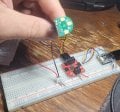
I have 3 of the J-class 6V LEDs in parallel, and a resistor to limit current through them. I had assumed they had a 0.7v drop forward voltage like regular LEDs / diodes, but I don't think that's right... Looking at the datasheet (https://downloads.cree-led.com/files/ds/j/JSeries-2835-6V-18V-Consolidated.pdf) it looks like they may be actually dropping 6v at 100mA? Someone correct me if I'm off...

Anyway, I'm trying to run this from an Arduino project where I'm actually getting 4.7v - 5v. When I hook the circuit up to the 5V USB port directly, they look perfect. When hooked up to the Arduino, where I get 4.7v due to a diode between the power rail and the USB port, they are so dim I can barely tell that they're on!

So, are they trying to drop 6v? The spec had a whole range of currents / lumens, how do I set light level? Should I not use a resistor at all for them, or should I have some other mechanism to limit current, or should I use some other LED entirely? How do other hobbyists use these? It's been 30 years since I've done any electronics, and I'm kind of lost.

Thanks in advance for the help!
 

geekoftheweek

Joined Oct 6, 2013
1,429
The typical forward voltage on the datasheet is the voltage the LED will drop... so yes it is 6V. If you are running them from 5V they should be fine by themselves. Anything more than 6V then you are going to have to add a current limiting resistor.
 

Thread Starter

bbroerman

Joined Nov 7, 2024
6
How are these LEDs connected to the Arduino?
I'm running an Adafruit QT Py ESP32-S3. it has a 5v output line from the USB port. There is a protection diode between the USB port and the 5v out pin, so the output on the 5v pin is actually 4.7v. I have a wire connecting that output pin to the circuit board that carries the 3 LEDs in parallel. (and of course one to ground) I'm guessing 4.7v isn't enough to drive them, but 5v is? They look perfect when powered directly from a USB plug...
 

Attachments

sghioto

Joined Dec 31, 2017
8,633
I don't see a connection on the red wire from the LED module to the breadboard.
Looks like you deleted the photo.
Why not just leave them connected at the 5volt source?
 

Thread Starter

bbroerman

Joined Nov 7, 2024
6
I don't see a connection on the red wire from the LED module to the breadboard.
Looks like you deleted the photo.
Why not just leave them connected at the 5volt source?
For that picture, i had reconnected the led board after taking it off to test the motor controller next to it... when I put it back on for the picture, I had it in wrong... I took a new picture with it plugged in correctly.

The 5v source for this test rig is my USB port on my hub. When I connect it to the hub directly, it works fine. Now, in the final project, I will have a 5v powerboost board connected to a LiPo battery, and will be distributing power directly from that, so I'm hoping it works fine in the final project. Right now I'm trying to just get everything understood properly.
 

Thread Starter

bbroerman

Joined Nov 7, 2024
6
Got that.
So is it a problem connecting directly to the 5 volt output.
on this one, yes... Wish it wasn't.

I am thinking of changing the LEDs on my boards from the 6v Cree to 3V Wurth Elektronik LEDs (I just ordered them). They run 15mA at 3v, with 3 in parallel, that's 45mA, so connected to a 4.7v source, I need to drop 1.7v, so a 37 ohm resistor. If I run them to the 3.3v output of the board instead of the 5v that's 6 ohm resistor to drop the 0.3v
 

Ya’akov

Joined Jan 27, 2019
10,226
Welcome to AAC.

I suspect the problem is limited current from the dev board. The voltage probably drops well below the 4.7V. Did you try just one LED?

By the way, the package probably contains 8 LED chips in series.
 

Thread Starter

bbroerman

Joined Nov 7, 2024
6
You can use a 6V constant-current driver that can output around 300mA.
So, would that be able to take in 3.3v - 4.7v as an input (depending on which voltage supply pin on the Arduino I run it from) and output 6v at a set current, or do I need to have 6v input? Do you recommend a particular driver?
 

Thread Starter

bbroerman

Joined Nov 7, 2024
6
Welcome to AAC.

I suspect the problem is limited current from the dev board. The voltage probably drops well below the 4.7V. Did you try just one LED?

By the way, the package probably contains 8 LED chips in series.
The PCB i have has 3 LED packages soldered on to it in parallel. All 3 are the Cree 6v white LEDs
 

Tonyr1084

Joined Sep 24, 2015
9,744
I'm running an Adafruit QT Py ESP32-S3. it has a 5v output line from the USB port. There is a protection diode between the USB port and the 5v out pin, so the output on the 5v pin is actually 4.7v. I have a wire connecting that output pin to the circuit board that carries the 3 LEDs in parallel. (and of course one to ground) I'm guessing 4.7v isn't enough to drive them, but 5v is? They look perfect when powered directly from a USB plug...
I don't know if I'm in error on this but a standard diode drops 0.7V, not 0.3V. So running 5V through a standard diode should drop the voltage to 4.3V, not 4.7V. At that low a voltage it's no surprise you can't get barely any light out of it.
So, would that be able to take in 3.3v - 4.7v as an input (depending on which voltage supply pin on the Arduino I run it from) and output 6v at a set current, or do I need to have 6v input? Do you recommend a particular driver?
You can't get more current than the source is able to deliver. If your supply can only deliver (just making up a number) 20mA at its rated voltage you can't get more than that. No matter what you do with the voltage. A resistive load at a given voltage and resistance will be X amps. If you drop the voltage the current will drop as well.
Got that.
So is it a problem connecting directly to the 5 volt output.
This question is valid. Assuming the 5V output is capable of delivering the desired current you can go this route. But the µP may not be capable of delivering the amperage needed. Which is why you see voltages dropping.
You can use a 6V constant-current driver that can output around 300mA.
Even better! Using a stand alone power source to deliver the needed current while the µP controls the output. I'm not sure how that might be accomplished but it is worth considering.

I have a high amperage air pump that I control using a 555 chip as a PWM source. That drives a FET and controls the main source (12V battery). There's no way the chip could EVER hope to drive that centrifugal compressor, it would burn the chip out.

Would suggest you start from scratch. Start by determining the necessary voltage and current for the LED's then decide how you want to control them. It's fairly safe to say the µP can't directly control the LED's. You'll need a different way of controlling them. Either by BJT or FET.

If any of these terms are unfamiliar to you:
µP = Micro-Processor
BJT = Bi-polar Junction Transistor
FET = Field Effect Transistor

FET's come in a variety of flavors for specific purposes. Choosing the right one is just as critical as getting everything else right.
 

YoungSky

Joined Oct 22, 2024
1
You need to provide at least 6V, a 5V supply is not enough. The best way to do this is to use a suitable constant current driver, not simply a resistor to limit the current. You can get a Boost Converter like the MT3608 (adjustable to 6V) and use a constant current circuit to limit the current to 100mA.
 
Top