Use voltage divided instead of external battery with a scr

Thread Starter

Momentory

Joined Sep 4, 2022
101
For educational propose only

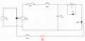
i have this circuit

- 12v dc battery
- boost converter up to 390v dc - dc
- capacitor 1000 uf 450v
- diode 10a10
- thyristor BTW69-1200 (I gt 8-80 mA / V gt 1.5v max)
cNCaI.png

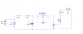
I managed to make this circuit work with external battery

But now i want to make the circuit work without this external circuit battery
Capture-4.PNG

Picsart_23-04-18_20-33-22-279.png

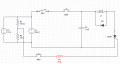
So i will do a voltage divider to get 1.5v from the 12v source but did not know exactly how the circuit should be

So here my prototype circuit, the voltage go to thyristor now should be 1.5v, i also add this 33ohm resistor to make the current to thyristor 40mA

Will this circuit is right ?
 

Thread Starter

Momentory

Joined Sep 4, 2022
101
We understand that, but the battery output and the converter output cannot be tied together as you show, since that's a short circuit.
This booster takes 12v from battery to give 200v output
Means they are not in parallel, the battery just give the booster 12v so the booster can output 200v
Not in parallel with the booster
 

BobTPH

Joined Jun 5, 2013
11,573
This booster takes 12v from battery to give 200v output
Means they are not in parallel, the battery just give the booster 12v so the booster can output 200v
Not in parallel with the booster
Then don’t draw it that way! Show the booster with two wires in and two out if isolated, or ground plus one wire in and one out if not.
 

Thread Starter

Momentory

Joined Sep 4, 2022
101
Remove R2, replace R3 with a short and increase R1 to 300 ohms. That will reduce drain on your battery significantly.
This wouldn't work, The battery 12V is connected directly to the booster not parallel

This booster needs 12v and 4A at least to run correctly, so i need to use this 12v 4A to run the booster and i need 1.5v - 40mA to run the thyristor
 

drjohsmith

Joined Dec 13, 2021
1,623
This wouldn't work, The battery 12V is connected directly to the booster not parallel

This booster needs 12v and 4A at least to run correctly, so i need to use this 12v 4A to run the booster and i need 1.5v - 40mA to run the thyristor
Can I check .
Last schematic I saw has the 12v in parallel with the high voltage. Which as others have said is wrong in so many ways .
It's a very dangerous circuit you have and I for one feel uncomfortable giving advice with that schematic as a basis
Can you produce a corrected one please .
 

MrAl

Joined Jun 17, 2014
13,728
For educational propose only

i have this circuit

- 12v dc battery
- boost converter up to 390v dc - dc
- capacitor 1000 uf 450v
- diode 10a10
- thyristor BTW69-1200 (I gt 8-80 mA / V gt 1.5v max)

View attachment 292402

I managed to make this circuit work with external battery

But now i want to make the circuit work without this external circuit battery
View attachment 292403

View attachment 292404

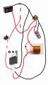
So i will do a voltage divider to get 1.5v from the 12v source but did not know exactly how the circuit should be

So here my prototype circuit, the voltage go to thyristor now should be 1.5v, i also add this 33ohm resistor to make the current to thyristor 40mA

Will this circuit is right ?
Interesting way to show the circuit.
 

BobTPH

Joined Jun 5, 2013
11,573
You misconception here is that you must have a 1.5V supply to trigger the the SCR. It can be triggered by a higher voltage through an appropriate resistor. Think of it the same way as running a 2V, 20mA LED from a 12V supply by using a resistor.
 

wraujr

Joined Jun 28, 2022
260
Starting withle "proposed" schematic, I would suggest the following.
(a) Move SW1 to the 12V+ side to provide on/off control.
(b) SW2 should be a momentary Normally-Closed (NC) to stop the SCR from conducting (i.e. stop motor)
(c) Properly draw your booster as a four (4) terminal device (VIN+/VIN-/VOUT+/VOUT-)
Now you are using a common ground, so VIN- and VOUT- connect together and too BAT-(12V) and all other GNDs
BAT+(12V) would connect to VIN+
Your boosted voltage is connected to VOUT+
Lastly, what exactly is L1? a motor, a solenoid. You could be looking at some high currents....
 

wraujr

Joined Jun 28, 2022
260
Also, from SCR datasheet, the gate only needs 2-15ma to trigger... So at 12V, a 1K resistor would be good to limit gate current.
IGTgate trigger current @VD=12 V; IT=0.1 A; Tj=25 °C; 2-15mA
 
Top