Use a 2N 3904 Transistor to switch 12v with MCU?

Thread Starter

haukeg

Joined Dec 9, 2018
66
Agreed!

It's hard to discuss circuits without schematics, and it's so much easier to use the schematics when they're laid out in the expected format.

Still, most new users on this forum didn't go to school for this stuff (to be clear, I didn't either) and so we have to expect weird drawings from time to time. Thankfully, a gentle judge in the right direction usually leads to improved drawings, as it did here.
Definitely appreciate the "nudge" and pointers @ebeowulf17 and @MisterBill2 - again a lot of this for me is about learning, and I just learned something new from this, thanks.
 

Thread Starter

haukeg

Joined Dec 9, 2018
66
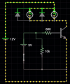
What I recommend is that you get a 12V Battery and create the circuit below. Put a push-button normally open (N.O.) switch where I've shown it above (to the right of the 3.3V power supply simulating a GPIO pin). Don't mess with the arduino or other power supply for now. Take a smaller step and get a circuit that WORKS in letting you turn your fans ON or OFF at the push of a button-- this will help you more than you think, and gives you something you can measure with a meter and gain an expectation from, to help you debug your other circuit.
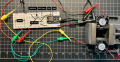
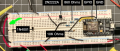
Great advice @BobaMosfet - I will remove the ESP compilation out of the tests. Below is a picture of my breadboard test. As far as I can determine, I have everything setup as described - but it's still not working. Maybe it's the overall grounding, or maybe the ESP. I will try again without that in the setup. If you see anything else that is obvious in my build, let me know.

1583181319178.png

Also, I too simulated the setup after the build failed, and found things worked as expected too. I must have an issue in my setup. Also, thanks for explaining more details about the NPN and MCU interface, and the purpose of it as a regulator, thats helpful conceptually.
1583181363526.png
 

MisterBill2

Joined Jan 23, 2018
27,874
Great advice @BobaMosfet - I will remove the ESP compilation out of the tests. Below is a picture of my breadboard test. As far as I can determine, I have everything setup as described - but it's still not working. Maybe it's the overall grounding, or maybe the ESP. I will try again without that in the setup. If you see anything else that is obvious in my build, let me know.

View attachment 200447

Also, I too simulated the setup after the build failed, and found things worked as expected too. I must have an issue in my setup. Also, thanks for explaining more details about the NPN and MCU interface, and the purpose of it as a regulator, thats helpful conceptually.
View attachment 200448
As with most diagnostics associated with locating problems, dividing a system is very useful. So now you know where the problem is not. One suggestion befor you go any farther is to measure the voltage between the transistor base and emitter, and also between the transistor collector and emitter. This will let you know if it is fully on, and what base voltage is needed to turn it fully on. That information will be handy when investigating how your MCU is trying to switch it on. AND, if you can now connect your GPIO to the base instead of the battery circuit, without disturbing the rest of the circuit that is working, you may have solved the problem already.
 

shjacks

Joined Apr 25, 2018
9
Hi, I am putting together a simple circuit to turn a fan on from an ESP8266 NodeMCU. I am providing 12v DC to a Buck Converter to drop to 5v for the MCU, but was hoping to have a simple gate for the 12v to fan using a 2N 3904 Transistor. Originally I was considering a Relay in place of the 2N 3904 Transistor, but felt like that was overkill at 12v? Any advice appreciate, thanks.
View attachment 199732
Yes the resistor is too high the Hfe of 2n3904 is around 50 so base current ~2ma. You goofed by using NPN because emitter will be .6V below base or are you hoping your 12 V fan will run at 4.5 volts (the transistor output in this circuit. Also the current dissipation of plastic 2n3904 type is not rated for high current or low on resistance. Ideally you would put the fan in the collector circuit and use a high current switching transistor like a 2N2905 (300ma, Hfe 100-300) or better an enhancement mode MOSFET like a VN88. I'm assuming a digital computer fan because it has less inductive chars. A regular fan would need snubber/protection circuit due to inductive voltage spikes.
 

shjacks

Joined Apr 25, 2018
9
Do you have the right pinout of the transistor? not sure of your breadboard's internal circuit arrangement but it appears some connections are not being made. If you bypass the Emitter/collector will the fans turn? Could be too high resistance in transistor, its voltage drop is .5 V at saturation but drive current is questionable. Some microcontroller circuits use open drain outputs with passive pull ups that only source 100 microamp not the 1-2 mA that transistor needs (based on transistor gain). Also you note 3V as if the GPIO pin outputs 3 V, but generally output is to a low current digital circuit. Perhaps a MOS transistor or darlington would work better. BTW, you mentioned that this was originally running a relay; what was the relay current that worked?
 

BobaMosfet

Joined Jul 1, 2009
2,211
As with most diagnostics associated with locating problems, dividing a system is very useful. So now you know where the problem is not. One suggestion befor you go any farther is to measure the voltage between the transistor base and emitter, and also between the transistor collector and emitter. This will let you know if it is fully on, and what base voltage is needed to turn it fully on. That information will be handy when investigating how your MCU is trying to switch it on. AND, if you can now connect your GPIO to the base instead of the battery circuit, without disturbing the rest of the circuit that is working, you may have solved the problem already.
@MisterBill2 - We are NOT turning the transistor fully on, by design. He needs < 300mA. The 2N2222 can switch up 800mA. His LM7805 regulator can only deliver < 400mA without overheating (see earlier posts in the thread).
 

ElectricSpidey

Joined Dec 2, 2017
3,346
I doubt if 4 mA base drive is enough.

Run a bypass across the emitter to the collector...the fans should run.

Double check that transistor pinout and connection. (looks wrong)
 

BobaMosfet

Joined Jul 1, 2009
2,211
Rewire your board. Try hooking your rails together so you have both sides of the breadboard powered and grounded- makes everything easier (see green arrow below):

1583190216435.png

Adjust placement of jumper wires and components accordingly.

A 2N2222:
1583190561593.png
When I look at your photo, it looks like both your emitter AND your collector are grounded. only the emitter should be grounded, and the image isn't clear enough for me to tell how your 3 resistors are connected- your base looks like it might be connected to one of them, but...? The collector should be connected to the negative side of both your motors and positive side of both your diodes.

Rewire it so it makes better sense, right now it's kind of all over the place. Good effort, but I think you're making it a little harder on yourself than it needs to be ;P
 
Last edited:

ebeowulf17

Joined Aug 12, 2014
3,307
Great advice @BobaMosfet - I will remove the ESP compilation out of the tests. Below is a picture of my breadboard test. As far as I can determine, I have everything setup as described - but it's still not working. Maybe it's the overall grounding, or maybe the ESP. I will try again without that in the setup. If you see anything else that is obvious in my build, let me know.

View attachment 200447

Also, I too simulated the setup after the build failed, and found things worked as expected too. I must have an issue in my setup. Also, thanks for explaining more details about the NPN and MCU interface, and the purpose of it as a regulator, thats helpful conceptually.
View attachment 200448
Looks to me like two resistors that are meant to be in series aren't connected. Counting resistors from top down, first and second are connected, but second and third aren't.
 

ebeowulf17

Joined Aug 12, 2014
3,307
Try hooking your rails together so you have both sides of the breadboard powered and grounded- makes everything easier (see green arrow below):

View attachment 200466

A 2N2222:
View attachment 200467
When I look at your photo, it looks like both your emitter AND your collector are grounded. only the emitter should be grounded, and the image isn't clear enough for me to tell how your 3 resistors are connected- your base looks like it might be connected to one of them, but...? The collector should be connected to the negative side of both your motors and positive side of both your diodes.
Good catch. Hard to tell, but looks to me like emitter and collector are reversed on the breadboard connections.
 

MisterBill2

Joined Jan 23, 2018
27,874
Great advice @BobaMosfet - I will remove the ESP compilation out of the tests. Below is a picture of my breadboard test. As far as I can determine, I have everything setup as described - but it's still not working. Maybe it's the overall grounding, or maybe the ESP. I will try again without that in the setup. If you see anything else that is obvious in my build, let me know.

View attachment 200447

Also, I too simulated the setup after the build failed, and found things worked as expected too. I must have an issue in my setup. Also, thanks for explaining more details about the NPN and MCU interface, and the purpose of it as a regulator, thats helpful conceptually.
View attachment 200448
The circuit in this post is incorrect, the 10K resistor is to remove the base charge when the drive is removed, and so it should be connected from the base to the emitter.
 

shjacks

Joined Apr 25, 2018
9
Rewire your board. Try hooking your rails together so you have both sides of the breadboard powered and grounded- makes everything easier (see green arrow below):

View attachment 200466

Adjust placement of jumper wires and components accordingly.

A 2N2222:
View attachment 200467
When I look at your photo, it looks like both your emitter AND your collector are grounded. only the emitter should be grounded, and the image isn't clear enough for me to tell how your 3 resistors are connected- your base looks like it might be connected to one of them, but...? The collector should be connected to the negative side of both your motors and positive side of both your diodes.

Rewire it so it makes better sense, right now it's kind of all over the place. Good effort, but I think you're making it a little harder on yourself than it needs to be ;P
EBC is used in round can transistors and a few plastic parts. The 2n2222 parts that we used were actually ECB which is more common among plastic parts.. TO-92 can be both. In TO-220 etc you can see that the middle connection is the bottom connection to the chip which is usually the collector.
 

MisterBill2

Joined Jan 23, 2018
27,874
@MisterBill2 - We are NOT turning the transistor fully on, by design. He needs < 300mA. The 2N2222 can switch up 800mA. His LM7805 regulator can only deliver < 400mA without overheating (see earlier posts in the thread).
The transistor needs to be fully saturated, not left in the linear mode. The voltage to the fans is supposed to bwe 12 volts, so the transistor must be fully on. And the regulator is not regulating the fan power, at least it is not supposed to be regulating the fan power. So I don't know which circuit you are looking at. The fans power directly from the 12 volt supply.
 

ElectricSpidey

Joined Dec 2, 2017
3,346
My observations...for what the're worth.

Beo is correct the resistors look like they do not connect.
The transistor is connected backwards.
Get rid of the 10k pulldown...not needed. the base will be driven low when the ESP goes low, and even in a high z state, 10k is not needed.
I still think 4mA base drive is too low.
 

MisterBill2

Joined Jan 23, 2018
27,874
I provided a circuit in post #66 based on Ground being zero (0), not -12V. 2N2222 is common-emitter configuration. Pay attention to the orientation of the diodes around the fans. The snubber diodes are wired backwards to deal with output from the fans not from the 12V.

The circuit I provided for the 2N2222 and motor control is correctly done (used in projects in real life), and works. Here is a simulation, so you can see values, using a 1-Ohm resistor in place of the motors so you can see how much current is being delivered through the transistor:

View attachment 200438

Voltage is 11.7 because of the BE junction on the transistor consuming 0.3V in this case where as my calculations assumed 0.7. 11.7+0.03 = 12V. You can see that with an 860-Ohm transistor on the base, 253mA is being delivered. You could raise that capacity by making it an 820 Ohm resistor. The motors/fans will use what they are going to use so long as they stay under what the transistor is allowing max.

Your GPIO pin is grounded by the MCU, and by the 10K-Ohm resistor I've shown. That is to drain possible current off the pin so it doesn't float when you are not outputting a voltage. Ensuring the transistor shuts off fully. When you output 3.3V on the pin, we are only drawing about 3mA through the 860-Ohm resistor. The base is powered by the MCU. The CE junction (where your fans are) is powered by your 12V Source and whatever current it can deliver.

Your Grounds should be all connected so that a common reference exists between all points of your circuit- arduino, fan-control circuit, and power-supply. Otherwise weird things can happen.

Understand that we are not using the 2N2222 solely as a switch in this circuit- it is not fully ON. We are only turning it on enough to allow 253mA. And then shutting if off fully if the 3.3V GPIO pin is off. It is _regulating_ the current flow between the CE junction.

What I recommend is that you get a 12V Battery and create the circuit below. Put a push-button normally open (N.O.) switch where I've shown it above (to the right of the 3.3V power supply simulating a GPIO pin). Don't mess with the arduino or other power supply for now. Take a smaller step and get a circuit that WORKS in letting you turn your fans ON or OFF at the push of a button-- this will help you more than you think, and gives you something you can measure with a meter and gain an expectation from, to help you debug your other circuit.

Here it is again- with the fans/motors:

View attachment 200441

Good luck! :p - Please continue to post your progress.
This explanation is very confused. First, Vbe does not subtract from the collector voltage . Next, and more important, the transistor is being used as a switch and so it needs to be fully saturated in order to not have excessive power dissipated as heat. In this aplication the transistor is being used as a switch, not as a linear amplifier.
 

Thread Starter

haukeg

Joined Dec 9, 2018
66
Thanks for all the thoughts. As many posted, you may be right, I think I have the 2N2222 reversed, so will give that a look. Thanks for that catch. Also will confirm my resistors are all connected for the 860 ohms (330, 330, 200) - I’m pretty sure I tested that series for overall resistance when building tho.

For reference, the ESP NodeMCU can put out 3.3v at around 12mA.

Will assess when home in a bit, and digest all the feedback more carefully, thanks.
 
Top