Use a 2N 3904 Transistor to switch 12v with MCU?

MisterBill2

Joined Jan 23, 2018
27,874
Thanks on the username- I admit I was at the first StarWars release.

"peak base current" - if you mean 'base' of transistor that's wrong. The base on the 2N2222 will be a fraction of that- the BJT isn't just a switch, it's a current amplifier. So, to give your circuit everything it could need, let's just shoot for 300mA.

so to recap:

FAN CALCS:
Loaded current (fan spinning): 88mA (R = E/I so: R = 12/.088; R = 136 Ohms : Likewise P=IE so: P = 12*0.088; P = 1.05W)
Stall current (fan prevented from spinning); 120mA (you can do the calcs as above for resistance & power-consumption)

2 fans in parallel, so current peak: ~240mA
A fan is an inductive load- if they don't have a snubber internally, you can use a 1N4002 in parallel with each fan.

2N2222 CALCS:
Ic = beta * (Ib) Collector current = gain * base current; 2N2222 gain is typically 100)
0.300 = (100 * Ib)
0.300 /100 = Ib
0.003 = Ib 3mA on the base will give you 300mA on the collector

Rb = (Vb - Vbe)/Ib (Resistor on Base = voltage on GPIO - what's lost through knee/ what we need on base - R = E/I)
Rb = (3.3-0.7)/0.003
Rb = 866.66 (Closest is 860 Ohms)

That lets your 3.3V GPIO pin control your 12V fans easily.

View attachment 200186

Now, regarding dropping 12V to about 7V for your LM7805, you can use this method:

View attachment 200189

You can reference the original document here:

http://www.idc-online.com/technical_references/pdfs/electronic_engineering/Voltage_regulators.pdf
Most motors draw their stall current at the instant that they are powered, before they start spinning. So that is the current at the first instant power is applied. It is also called "locked rotor current" for induction motors. So you need to be aware of that.
 

MaxHeadRoom

Joined Jul 18, 2013
30,752
For my applications like that that switches a motor full on from zero RPM, I tend to use a DC rated relay.
And reserve the Mosfet control when using a ramped up PWM.
For large motors, the relay would have arc blow out on the contacts.
Max.
 

MisterBill2

Joined Jan 23, 2018
27,874
For my applications like that that switches a motor full on from zero RPM, I tend to use a DC rated relay.
And reserve the Mosfet control when using a ramped up PWM.
For large motors, the relay would have arc blow out on the contacts.
Max.
Max, let me copy the TS here: "I tested the fans and found ~88mA on free current and about ~120mA on stall current. " So it does not seem that these are high power induction motors. More like small computer fan motors. And they will only be running at max speed i this application. So no large contactors needed here. And because of the control scheme, not even spike suppression diodes needed.
 

BobaMosfet

Joined Jul 1, 2009
2,211
Most motors draw their stall current at the instant that they are powered, before they start spinning. So that is the current at the first instant power is applied. It is also called "locked rotor current" for induction motors. So you need to be aware of that.
stall at start and stall by retarding rotation is the same- my description still stands.
 

MisterBill2

Joined Jan 23, 2018
27,874
stall at start and stall by retarding rotation is the same- my description still stands.
The intent of my comment was to explain that it was only for a very short time. So a voltage regulator would need to be able to deliver that current without going into a shut-down mode, or some other latched overload mode. That sort of occurrence gave me problems on one test stand that I designed a few years back.
 

Thread Starter

haukeg

Joined Dec 9, 2018
66
Thanks on the username- I admit I was at the first StarWars release.

"peak base current" - if you mean 'base' of transistor that's wrong. The base on the 2N2222 will be a fraction of that- the BJT isn't just a switch, it's a current amplifier. So, to give your circuit everything it could need, let's just shoot for 300mA.

so to recap:

FAN CALCS:
Loaded current (fan spinning): 88mA (R = E/I so: R = 12/.088; R = 136 Ohms : Likewise P=IE so: P = 12*0.088; P = 1.05W)
Stall current (fan prevented from spinning); 120mA (you can do the calcs as above for resistance & power-consumption)

2 fans in parallel, so current peak: ~240mA
A fan is an inductive load- if they don't have a snubber internally, you can use a 1N4002 in parallel with each fan.

2N2222 CALCS:
Ic = beta * (Ib) Collector current = gain * base current; 2N2222 gain is typically 100)
0.300 = (100 * Ib)
0.300 /100 = Ib
0.003 = Ib 3mA on the base will give you 300mA on the collector

Rb = (Vb - Vbe)/Ib (Resistor on Base = voltage on GPIO - what's lost through knee/ what we need on base - R = E/I)
Rb = (3.3-0.7)/0.003
Rb = 866.66 (Closest is 860 Ohms)

That lets your 3.3V GPIO pin control your 12V fans easily.

View attachment 200186

Now, regarding dropping 12V to about 7V for your LM7805, you can use this method:

View attachment 200189

You can reference the original document here:

http://www.idc-online.com/technical_references/pdfs/electronic_engineering/Voltage_regulators.pdf
This is fantastic @BobaMosfet - thanks so much for the details feed back. Super helpful for someone trying to learn from this, I’m used to simple pointers alone. Hope you'll accept a thank you with the attached - figure a name like that deserves a rad user pic!

Really appreciate the schematic for the fan switch, thats awesome. Looks like a great option for ditching the 12v relay.

Also from your other post, I have dug in a bit on the 2N3055, thanks for the tip on that. Were you thinking that could be a good option for switching the dehumidifier 9V 2.5A? Sounds like a better way to go over the relay.

As I dug in on the 2N3055, I saw a number of posts on its amplification capabilities. Now while I can use one for switching, I was wondering if it would make sense to follow the suggestion from @MisterBill2 on using 9V as the power supply and amplifying it to get the 12v needed for the fans? That would reduce the stepping down for the 5V and maintains the Amperage on the 9V for the humidifier. Just a thought, not sure if that is feasible.
 

Attachments

BobaMosfet

Joined Jul 1, 2009
2,211
@haukeg Thank you very much for the awesome avatar!

Really very glad to help.

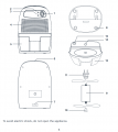
If you want 9V @ 2.5A - use the existing power-supply for the unit (Item #9):

1583026328050.png


Per the manual above, #10 plugs into #7. Simply put your 2N3055 circuit between #7 & #10 to switch current on or off.
 

Thread Starter

haukeg

Joined Dec 9, 2018
66
@haukeg Thank you very much for the awesome avatar!
You're welcome @BobaMosfet - glad you dig it.

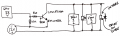
So I tried a quick breadboard of the schematic you gave me for the fan switch, however I used 1N4001 instead of 1N4002 diodes assuming that wouldn't matter. I sketched up how I wired it on my breadboard below, did I miss anything? When I put 3.3v to the base, nothing happens.
1583034654645.png

Also, did you have any thoughts on the 2N3055 as an amplifier for 9V to 12v for the fan (see #66).
Thanks!
 

MisterBill2

Joined Jan 23, 2018
27,874
The circuit shown in post #68 needs to have the return connection of the GPIO signal shown. And there is a problem with the direction of the transistor, in that with an NPN device the collector is usually on the more positive side of the circuit. And in that drawing positive is shown on the bottom. AND, a transistor will not simply amplify a voltage. It can only switch it or lower it.
 

Thread Starter

haukeg

Joined Dec 9, 2018
66
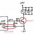
Hmm, thanks @MisterBill2. Guess I’m not sure how I should be grounding the GPIO? I assume riding it in with the 12v ground isn’t good because those are different sources? And can try reversing the 2N2222. See below, is that more like what you’d recommend?
1583087392259.jpeg
 
Last edited:

ebeowulf17

Joined Aug 12, 2014
3,307
Hmm, thanks @MisterBill2. Guess I’m not sure how I should be grounding the GPIO? I assume riding it in with the 12v ground isn’t good because those are different sources? And can try reversing the 2N2222. See below, is that more like what you’d recommend?
View attachment 200347
Looks to me like you've got it right.

I wouldn't label that lower node as "-12V" because that implies that you've got a dual supply with both +12 and -12, for a total of 24V. If I've read everything up until this point correctly, you've got a 12V supply, so that lower node should simply be marked "ground," "common," or even "0V." There are countless debates about precisely how these things should be labelled, because there are many different types of "grounds" and "commons," but in my opinion there's no need to split hairs on which one you've got here I'm pretty sure it's not "-12," but any of the other labels would probably suffice for this circuit.

Anyway, other than that labelling question I think you've got it. I don't think you should reverse the NPN transistor. I think maybe @MisterBill2 was just thrown off by your original schematic showing lower and higher voltages in a non-standard orientation. I believe you had the transistor correct all along and you were just missing the common ground. Now that you've reoriented the drawing, it should be clearer.
 

ebeowulf17

Joined Aug 12, 2014
3,307
P.S. There are times when the power supplies for two circuits need to be completely isolated, without a common ground, but in that case more complicated interfaces are required (often opto isolators.) In your case, I don't see any reason not to share grounds, and it allows for the much simpler, single-transistor control circuit.

This simple interface only works if the grounds are shared, otherwise there's no return path for base current. Current flows in complete loops, so if you want current to flow out of the GPIO and through the base of the transistor, it must then loop back through a shared ground to its source in the microcontroller.

Or, to put it another way, voltages only exist as relative measures. So, you need forward voltage to bias the base of the transistor and turn it on. Without a common ground between the two voltage systems, they "float" relative to one another. When the GPIO tries to push 3.3V through the transistor, instead it just drives the whole microcontroller sub-circuit down 3.3V compared to the 12V fan sub-circuit and no current flows.

Sorry, I don't think either of these explanations is very clear, but rest assured that you either need common grounds, or you need special devices for interfacing isolated systems.
 

MisterBill2

Joined Jan 23, 2018
27,874
Hmm, thanks @MisterBill2. Guess I’m not sure how I should be grounding the GPIO? I assume riding it in with the 12v ground isn’t good because those are different sources? And can try reversing the 2N2222. See below, is that more like what you’d recommend?
View attachment 200347
The polarities in post 70 are OK, but in post 68 they were reversed. And as for labels, as long as we all understand that there is one 12 volt supply why confuse things?? And in order for that GPIO terminal to bias the transistor ON, you will need to connect the return (output common) to the emitter line., as shown in post #70.
 

Thread Starter

haukeg

Joined Dec 9, 2018
66
Sorry, I don't think either of these explanations is very clear, but rest assured that you either need common grounds, or you need special devices for interfacing isolated systems.
Not at all, super helpful explanation and I appreciate you sharing, again I’m still learning a lot of this so that really helps!
Also makes sense on the Ground, 0v, -12v points, I guess I’ve seen it done so many ways it was confusing and I am never sure when to use what. But your explanation helped a bit. I guess ultimately what I wanted to communicate was those connect to the negative lead from my 12v supply. Maybe someday I’ll get it
 

ebeowulf17

Joined Aug 12, 2014
3,307
The polarities in post 70 are OK, but in post 68 they were reversed.
Nope - polarities are the same in both. Look more closely at the markings on the 12V supply in post 68. Positive on the bottom, negative on top. If you trace out all the connections, the only difference between 68 and 70 is that one ground connection.
 

MisterBill2

Joined Jan 23, 2018
27,874
Nope - polarities are the same in both. Look more closely at the markings on the 12V supply in post 68. Positive on the bottom, negative on top. If you trace out all the connections, the only difference between 68 and 70 is that one ground connection.
OK, the drawing in post#68 was not drawn in the normal, conventional, arrangement. Normally positive is above. Any other arrangement of things tends to cause errors to happen. There is a valid reason for following drawing conventions.
 

ebeowulf17

Joined Aug 12, 2014
3,307
OK, the drawing in post#68 was not drawn in the normal, conventional, arrangement. Normally positive is above. Any other arrangement of things tends to cause errors to happen. There is a valid reason for following drawing conventions.
Agreed!

It's hard to discuss circuits without schematics, and it's so much easier to use the schematics when they're laid out in the expected format.

Still, most new users on this forum didn't go to school for this stuff (to be clear, I didn't either) and so we have to expect weird drawings from time to time. Thankfully, a gentle judge in the right direction usually leads to improved drawings, as it did here.
 

BobaMosfet

Joined Jul 1, 2009
2,211
Hmm, thanks @MisterBill2. Guess I’m not sure how I should be grounding the GPIO? I assume riding it in with the 12v ground isn’t good because those are different sources? And can try reversing the 2N2222. See below, is that more like what you’d recommend?
View attachment 200347
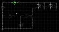
I provided a circuit in post #66 based on Ground being zero (0), not -12V. 2N2222 is common-emitter configuration. Pay attention to the orientation of the diodes around the fans. The snubber diodes are wired backwards to deal with output from the fans not from the 12V.

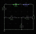
The circuit I provided for the 2N2222 and motor control is correctly done (used in projects in real life), and works. Here is a simulation, so you can see values, using a 1-Ohm resistor in place of the motors so you can see how much current is being delivered through the transistor:

1583167773275.png

Voltage is 11.7 because of the BE junction on the transistor consuming 0.3V in this case where as my calculations assumed 0.7. 11.7+0.03 = 12V. You can see that with an 860-Ohm transistor on the base, 253mA is being delivered. You could raise that capacity by making it an 820 Ohm resistor. The motors/fans will use what they are going to use so long as they stay under what the transistor is allowing max.

Your GPIO pin is grounded by the MCU, and by the 10K-Ohm resistor I've shown. That is to drain possible current off the pin so it doesn't float when you are not outputting a voltage. Ensuring the transistor shuts off fully. When you output 3.3V on the pin, we are only drawing about 3mA through the 860-Ohm resistor. The base is powered by the MCU. The CE junction (where your fans are) is powered by your 12V Source and whatever current it can deliver.

Your Grounds should be all connected so that a common reference exists between all points of your circuit- arduino, fan-control circuit, and power-supply. Otherwise weird things can happen.

Understand that we are not using the 2N2222 solely as a switch in this circuit- it is not fully ON. We are only turning it on enough to allow 253mA. And then shutting if off fully if the 3.3V GPIO pin is off. It is _regulating_ the current flow between the CE junction.

What I recommend is that you get a 12V Battery and create the circuit below. Put a push-button normally open (N.O.) switch where I've shown it above (to the right of the 3.3V power supply simulating a GPIO pin). Don't mess with the arduino or other power supply for now. Take a smaller step and get a circuit that WORKS in letting you turn your fans ON or OFF at the push of a button-- this will help you more than you think, and gives you something you can measure with a meter and gain an expectation from, to help you debug your other circuit.

Here it is again- with the fans/motors:

1583168792503.png

Good luck! :p - Please continue to post your progress.
 
Last edited:
Top