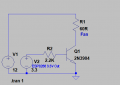
Voltage dividers are not used to power devices...choose a 7805 TO220 regulator, your micro will thank you for it, considering it will have *enough to deal with driving a motor. (*RFI and other noise)
Good to know, that is what the root of my question was about - whether using a voltage divider to power an MCU was a good idea. Since I am not driving the motor from the MCU, do you still suggest the 7805 with heat/efficiency downsides over a Buck Converter? It also seems like some of the other suggestions like the 2N3904, 2N2222A or 2N7000 could work since the ESP8266 NodeMCU draws <200mA of current?
Mostly.\, digital processors are supplied by switching type power supplies. Even the 3.3 volt systems can tolerate a few millivolts of noise. And to keep the motor noise out, use an opto-isolator and a saturated FET switch transistor.
While V and I are important you can't have both without W. The 78L05 is limited to 700mW so it depends on just how much current the ESP module draws. The T-220 cased LM340T5 does not have a W rating and is noted as "internally limited". Which means it will give up to 2.2A without failing IF properly heatsinked. Costs more than a penny but still rather cheap and more robust. If this is for actual use and not just an exercise I would wholeheartedly recommend a regulator.
VIN: This board can be powered by an external power supply by using this pin. Supply a voltage between 3.3V to 12V to this pin and the linear voltage regulator on the board will power the board.
According to this, you don't need a regulator, the ESP already has one built-in. The GPIO however is 3.3V to control a switching xstr. You need to find the ESP specification for the current that can be sourced from the GPIO pin???
VIN: This board can be powered by an external power supply by using this pin. Supply a voltage between 3.3V to 12V to this pin and the linear voltage regulator on the board will power the board.
According to this, you don't need a regulator, the ESP already has one built-in. The GPIO however is 3.3V to control a switching xstr. You need to find the ESP specification for the current that can be sourced from the GPIO pin???
Thanks @SamR - Unfortunately I have read a number of posts where others have tried using the ESP @ 12v and the regulator doesn't hold up well. See thread here.
I just finished rebuilding a 40 year old alarm system that uses old school sounders such as a classic motor driven siren, and it took a hell of a lot more than opto isolation and saturated transistors to keep the noise from scrambling the processor, despite the fact that they are located quite a distance from the box.
In the end it took RF chokes...clip on ferrites and back EMF diodes to suppress the noise enough to keep the micro from freaking out.
Since you mentioned Node MCU I assume this is what you have: ESP8266 NodeMcu ESP8266 Module. The ESP8266 chip itself uses a 3.3V power supply voltage. With the board the Vin can be 5 volts as the board provides a regulator. Keep in mind the I/O pins on the board are 3.3 volt pins. With that in mind any digital out will be 3.3 V and not 5.0 V. Typical 12 volt fans like those found in home computers will draw about 160 mA @ 12 V. Using a transistor I would likely use a 2N2222 rather than a 2N3904 simply to allow more overhead but if you are sure you fan will not be much over 100 mA the 2N3904 is just fine. The below is how you want it configured and what people have been pointing out. I would just put a common LM7805 off the 12 VDC with a few caps as shown in the data sheet. You might to also put a 0.1 uF cap across the fan motor in the interesting of suppressing noise.
Try about a 2.2 K base resistor and if you haven't gotten it yet the 2N7000 MOSFET would really do well for your application.
When the fan is running then its resistance is 60 ohms and its current is 200mA. When the fan starts then its current is about 1A that will blow up the little low current 2N3904.
If a transistor is used as a switch then it must saturate. A saturated transistor has a base current that is 1/10th the collector current so the 2.2k base resistor value is much too high. (3.3V - 0.8V)/20mA= 125 ohms for the motor to run, 25 ohms for it to start. The ESP cannot provide that much current.
A little 2N7000 needs a gate-source voltage of 10V to fully turn on. With a gate-source voltage of only 3.3V then some 2N7000 Mosfets will not conduct enough (2mA?).
The real bugaboo here is the 200mA @ 12V for the fan which the switch will have to handle. You may need to consider using a FQP30N06L which is a TO-220 Logic Level MOSFET. The starting input surge and throughput W capacity for a fan appears to be too much for a TO-92 cased device. The FQP30N06L can handle it and allow using the 3.3V on its gate.
I just finished rebuilding a 40 year old alarm system that uses old school sounders such as a classic motor driven siren, and it took a hell of a lot more than opto isolation and saturated transistors to keep the noise from scrambling the processor, despite the fact that they are located quite a distance from the box.
In the end it took RF chokes...clip on ferrites and back EMF diodes to suppress the noise enough to keep the micro from freaking out.
OK on the tough job of keeping the noise out. Yes, optos are a first line, but they will not help enough when all tghe wires are bunched into one conduit, and the power neutral is shared. Right now I have a noise in a PA system in a church. Of course the sound system is next to the light dimming panel with a dozen 15 amp feeds and a dozen 200 watt triac dimmers. And all the power runs 30 feet in a piece of steel conduit. And not enough neutrals. No design is so good that fools can't mess it up. AND, "You Can't Fix Stupid." Sorry about raging away, folks.
Thanks for the many tips and suggestions. It seems like there are transistor options if I get my calc's right, but the ripple was one of the reasons I first considered a Buck Converter. I am not an EE and am trying to learn some basic ways to power a number of devices off a single power supply.
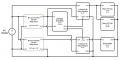
I didn't state this earlier, but I am looking for a couple powering options off my main 12V DC with this project. I plan to use a portable dehumidifier that runs on 9V - along with 2 fans with very low current draw - micro PC fans (see simplified wiring diagram below). I plan to program a schedule to run the fans (together) and the humidifier at specific times. Originally, my question was about using Buck Converters vs. transistors/MOSFETS, etc. as an alternative. I understand Buck's are possibly overkill and an expense that isn't necessary, but wanted to get some advice on the general concept.
The relay's I have trigger at 3-5V so I should be fine with the ESP8266 GPIO 3.3v out (on High) - but maybe there are alternatives to using a relay I should consider? I also wanted to confirm that a power supply @ 3A can power everything in my circuit (need help on calculating current across). I really want to learn through this so I appreciate the advice, patience and time from everyone on this forum - thanks!
Those 5 volt relays don't work well at all when driven with 3.3 volts which is what you get with the ESP8266 GPIO pins. If I were you and only had those two channels to worry about I would use a level shifter. Get 4 channels for under $3.00 USD. I see where they are 5 volt powered relay modules but they don't work well with the 3.3 V logic for turning them On/Off.
I am trying to imagine what sort of dehumidifier runs on 9 volts DC at low power. ALL of the dehumidifiers that I have seen use a refrigeration compressor and at least one fan, and draw at least 2 amps from the 120 volt mains.
So a description of a package that uses 9 volts at low power will be very educational for me.
I would use the buck to step down to 9 volts. then use a 5 watt Zener to drop down to the ESP voltage. (The onboard regulator in the ESP will deal with ripple)
I would use logic level MOSFETs to switch the fans and the de-humidifier.
As far as the "noise" I was thinking "motor" in my previous posts, but those micro PC fans should be easy enough to clean up using caps and diodes.
Don't know about the de-humidifier.
And 3 amps should handle everything...but with no margin.
I am trying to imagine what sort of dehumidifier runs on 9 volts DC at low power. ALL of the dehumidifiers that I have seen use a refrigeration compressor and at least one fan, and draw at least 2 amps from the 120 volt mains.
So a description of a package that uses 9 volts at low power will be very educational for me.
I would use the buck to step down to 9 volts. then use a 5 watt Zener to drop down to the ESP voltage. (The onboard regulator in the ESP will deal with ripple)
I would use logic level MOSFETs to switch the fans and the de-humidifier.
As far as the "noise" I was thinking "motor" in my previous posts, but those micro PC fans should be easy enough to clean up using caps and diodes.
Don't know about the de-humidifier.
And 3 amps should handle everything...but with no margin.
Those 5 volt relays don't work well at all when driven with 3.3 volts which is what you get with the ESP8266 GPIO pins. If I were you and only had those two channels to worry about I would use a level shifter. Get 4 channels for under $3.00 USD. I see where they are 5 volt powered relay modules but they don't work well with the 3.3 V logic for turning them On/Off.
Thanks @Reloadron - I have found powering the Relay with separate power (5v as shown in the schematic) has worked reliably, then using the 3.3v HIGH logic from the ESP GPIO to trigger IN - but the ESP IN & 5v Vin/GND are separated via removing a jumper. Not sure if this address your concern, but definitely have found that powering the Relay via 3.3v does not work. Thanks for pointing out the potential issue.
I am trying to imagine what sort of dehumidifier runs on 9 volts DC at low power. ALL of the dehumidifiers that I have seen use a refrigeration compressor and at least one fan, and draw at least 2 amps from the 120 volt mains.
Would the Peltier device work. I had one that came out of a drinking water cooler back in 1964, that had a copper water tank glued to one side and a heat sink on the other . Ran on 12 volts DC. Just reverse the polarity and it would heat the water. Should work great for a dehumidifier. I think the DC to Dc converter does a great job of powering MCU's. They cost about $2.00 ea on Amazon and allow almost any wallwart type power supply to work. Also the IGBT's work and will switch a lot of current. I use the IRFZ44 (about 9 amps @ 5 volts (gate)) and the FQP30N06L (3.3 volt version) driven from an Arduino, ESP8266-12E NodeMCU, and the Raspberry Pi Zero W for my master clock projects. Here is the RPI backup schematic using two on them.
See also: https://forum.allaboutcircuits.com/...-itr-and-ibm-impulse-secondary-clocks.166089/

 Facebook
 Google
 GitHub
 Linkedin