There will usually be a specification in the datasheet that tells you how close the output can come to either power rail. In some cases, the difference could be significant as it is for the ancient 741. In other cases, it could be a few millivolts as it is for some rail-to-rail opamps. In this section of the datasheet for the TL071/TL072 it shows ± 13.5 V outputs assuming a load of 10kΩ and ± 15 V supply rails. This would not be considered a rail-to-rail part.
There will usually be a specification in the datasheet that tells you how close the output can come to either power rail. In some cases, the difference could be significant as it is for the ancient 741. In other cases, it could be a few millivolts as it is for some rail-to-rail opamps. In this section of the datasheet for the TL071/TL072 it shows ± 13.5 V outputs assuming a load of 10kΩ and ± 15 V supply rails. This would not be considered a rail-to-rail part.
You can place the GND reference voltage to any place you wish on the 9V battery supply. Mid-point seems to be a natural place to put it.
Unfortunately, the simulator I use does not have the proper COM symbol.
That should be considered a "working hypothesis". You would be wise to verify it. Another reasonable hypothesis is that the difference between the rail and the output voltage will be about 1.5 V (typical) and 3V (worst case) with the aforementioned 10kΩ load.
So I added some stuff onto this circuit to power an 2-conductor condenser mic. C6 and C8 are 9v power supply filters and then R10/R11 is a voltage divider to put 4.5V across the mic. It still simulates in Eagle this way. I'll paste the original mic preamp at the end, I will eventually add that in too but I wanted to test just the HPF without the preamp first.
I wonder if the voltage divider circuits could be shared?!?
Any thoughts?
YES! The above circuit worked without the preamp opamp - just the HPF, 4.5v mic power and 9v power supply filtering. I breadboarded it up and I could hear it. Pot at full 47k and the low E was full and strong and very feedback prone. Roll the pot down through it's range and the low E goes away. Still there, just super thin at the end, which makes sense, simulation says should have about -40dB on the low E at 0 on the pot.
@Audioguru again , I know you say a mic needs amplified 25-50x. But based on my experience with breadboarding the preamp circuit, it doesn't need much. Yes the preamp will help and give me more flexibility with mixing it in with the primary pickup. But the signal is not that much lower than my primary pickup. I think setting the gain on the preamp circuit to 10x would be plenty.
Thank you ALL for your help. Now I'll move onto adding the preamp circuit into the above.
Circuit: Mic input on the right, output on the left.
10k voltage divider on the top left. HPF dual pot in the middle. 5k's soldered to pot.
100k voltage divider for mic input on the top right.
Here is the mic power, preamp and HPF using 2 op amps, or a dual op amp like the TL072. This simulated the same as the previous circuit, only the band pass voltage was up +24.6 dB (10x) instead of +3.6 lb (pot at 0). Now I need to figure out how to model a potentiometer.
Does anybody sell opamps that have "typical" specs?
If you want typical specs then buy a bunch and measure all of them, then you might find one with "typical" specs.
I always design circuits using minimum and maximum specs so that ALL of my circuits work perfectly, not just the ones that have parts with "typical" specs.
@Ian0
I've been digging through the literature on the DS3903. A couple questions:
1) Curious why the tech note says the fc = sqrt(2)/[2*pi*R*C]. I've never seen the sqrt(2) before in that formula.
2) The 9 pot terminals (L0, L1, L2, W0, W1, W2, H0, H1, H2) are the outputs. So what type of device would INPUT to SDA, SCL, A0?
3) I think the circuit in the tech note (LPF), could be altered to be a HPF like in this thread. In the attached diagram, POT0 and POT2 would become caps, and C2, C3 would become the digital pots. And similarly how C3 is 2*C2, for a HPF arrangement ideally the resistor to ground is twice the other resistor. Not sure if that can be programed in or not.
SCL and SDA indicate that it is a I2C interface. There is a huge variety of digital pots, you can get I2C and SPI interfaces to connect to a microcontroller, a single clock and up/not_down input and separate push button inputs for up and down.
Something I'm trying to understand some of the capacitance values. Like for instance, C9 and C5 seem to be doing similar things (opamp de-couping caps?) but one is 22u and the other 100u. And C4 seems similar too. C6 and C8 are more directly related to the power supply AC ripple currents I think. How are these caps sized?
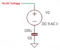
C6 is in series with the power supply but it does not pass DC so the circuit does not work.
C6 should be in parallel with the power supply to filter it.
C9 and C5 produce severe clipping distortion while they are partially charging for longer than 2 seconds after the power supply is turned on. But they form highpass filters, then you should calculate their low cutoff frequency with R15 and R8.
If the power supply has low ripple then the capacitance of C8, C6 and C4 are fine.
 Facebook
 Google
 GitHub
 Linkedin