Universal Active Filter IC's

Ian0

Joined Aug 7, 2020
13,158
It would be easy to make a switched 4th-order Butterworth highpass filter but it is not two 2nd-order circuits in series that would produce a droopy Bessel response (not a sharp-corner Butterworth response). You must lookup the resistor ratios for it to be Butterworth..
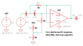
You can still get the MF10, which will synthesize two state-variable filters.
https://www.ti.com/lit/ds/symlink/m...563&ref_url=https%3A%2F%2Fwww.mouser.co.uk%2F
The two cutoff frequencies will be identical, and you can set the Qs of each section independently.
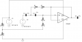
All you need is a variable clock frequency (555, perhaps?) to set the cutoff frequency.
The audio quality isn't as good as an op-amp filter.
 

Papabravo

Joined Feb 24, 2006
22,084
Well done on getting this far so quickly. Even with equal resistances (R1+R2) = (R3+R4), you should see some roll off at low frequency. So, there must be another error. Where is the feedback from output back to the - (non-inverting) input? Recheck the drawing in post #30.
 

Thread Starter

rpschultz

Joined Nov 23, 2022
838
Ian0 did point out that I needed R2 to go to the output, fixed.
C3 right? Cyan color? I don't know what else it could be. I pasted the opamp stuff at the bottom.

1671833905436.png1671834003453.png

* Autodesk EAGLE
* BASIC OP AMP MODEL
* Device Pins In+ In- vdd vss Vout
* vdd vss unused in this model!!
.SUBCKT opamp 1 2 vdd vss vout
*
* INPUT
RIN 1 2 1e9
*
* AMPLIFIER STAGE: GAIN, POLE, SLEW
* Aol=10000, fu=1000000 Hz
G1 0 10 VALUE = { 1e-2 * V(1,2) }
R1 10 0 1e6
C1 10 0 1.59e-9
*
* 2ND POLE
G2 0 20 10 0 1e-6
R2 20 0 1e6
C2 20 0 3.3e-14
*
* 3RD POLE
G3 0 30 20 0 1e-6
R3 30 0 1e6
C3 30 0 3.3e-14
*
* OUTPUT STAGE
EBUFFER 80 0 30 0 1
ROUT 80 vout 100
.ENDS opamp
 

Thread Starter

rpschultz

Joined Nov 23, 2022
838
I think it's the model. It says:
* vdd vss unused in this model!!
The opamp isnt getting power. I need to find a better model I think
 

michael8

Joined Jan 11, 2015
472
>> Another level of complexity would be use a single pot to be read by an MCU and do the filtering digitally in software.
>This might be feasible for a low pass application with an analog anti-aliasing filter. This is a high pass application where
> all the frequencies above the Nyquist limit will be folded back into the baseband.


I wonder if it would be possible to select the low frequencies (analog and/or DSP) and then subtract them from
a copy of the original signal? So the filtering never has to deal with the high frequencies.
 

Papabravo

Joined Feb 24, 2006
22,084
I think it's the model. It says:
* vdd vss unused in this model!!
The opamp isnt getting power. I need to find a better model I think
I don't think it is the model. I think the .subckt is looking for net names.
Why does it seem that everybody blames the model as a first hypothesis?
 

Thread Starter

rpschultz

Joined Nov 23, 2022
838
Ok so R5//R6 is a voltage divider and will always be R5/2. But R1 and R3 are always the same if a dual gang pot. So I’m not sure how that equation ever works.
 

Audioguru again

Joined Oct 21, 2019
6,826
R5//R6 means that R5 and R6 are electrically in parallel.
R5 and R6 make the 4.5V bias for the opamp input. Their parallel resistance is 4k ohms which is in series with R3 to make double the resistance of R1 for a Butterworth response.
 

Audioguru again

Joined Oct 21, 2019
6,826
If you use a double gang pot then simply make the opamp have a gain of about 1.6 times, then the two frequency setting resistances can be the same to make a Butterworth response.

I corrected the note in my schematic. When the opamp has a gain of 1 then the resistance to ground must be double the feedback resistance to make a Butterworth response.
 

Attachments

Ian0

Joined Aug 7, 2020
13,158
That's because SPICE only measures the AC component.
Since an opamp input draws a very low current then the 4.5V can be two 22k resistors in series producing 4.5V and a 22uF capacitor to ground making a very low impedance.
You used 100k, but you forgot the capacitor. Without the capacitor the 100k resistors (in parallel because they both go to AC ground) are in series with your frequency setting resistors.
Plot the voltage at a few other points, such as the non-inverting input of the op-amp and see what is happening there.
 

Audioguru again

Joined Oct 21, 2019
6,826
The two 100k voltage divider resistors are in parallel to the signal then are a 50k resistance to ground.

The simulation does not work since the input is 1V but the output which also should be 1V measures only a few hundredths of a volt.
Your frequency response shows only high frequencies, not the low frequencies you want cut.

My simulation program works perfectly:
 

Attachments

Top