understanding circuit logic of PID blocks in ltspice circuit

Thread Starter

yef smith

Joined Aug 2, 2020
1,447
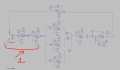
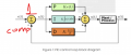
Hello, There Is this great working PID system I am trying to understand its logic.I am trying to compare this circuit to the classic diagram of PID feedback system.
Two questions:
1. what is the analog logic of block I designates as 1,how can I analize its tranfer function?
2. Why are they inverting the output signal before going into PID?
https://github.com/HemakanthNatkuna...t/blob/main/EC5030_DesignProject_2020e050.pdf
Ltspice and photos are attached.
 

Attachments

ericgibbs

Joined Jan 29, 2010
21,391
Hi yef,
I would say that the Github PID is overcomplicated.
The U5 and U6 OPA's could be removed and the U4 configured as a Non Invert OPA
Feed the Set Point signal into the Non Inv of U4 and also the output of U1 also into the Non Iv input of U4.
Use resistors to configure it as a summing amplifier.
I see also he has transposed the location of the I and D modules.

On you circuit where will the error signal be derived??

E
 

Thread Starter

yef smith

Joined Aug 2, 2020
1,447
Hello Eric, what is the logic of all these inverters stages 1 and 3?
how does it make our systems feedback functioning?
Thanks.

1741369427174.png
 

ericgibbs

Joined Jan 29, 2010
21,391
hi yef,
The posted PID is only a closed loop PID.
How and where are you measuring the error voltage for the Plant you wish to control?

The U6 OPA error pathway input should be connected in some way to the Plant being controlled.
So that when you set the SetPoint, the Output of your PID circuit drives the Plant to match the Setpoint setting.
The difference between the Setpoint and Measured state of the Plant is the error signal which fed back into the PID input.

The PID will drive the Output until the Plant error versus the Setpoint becomes Zero.

E
 

ericgibbs

Joined Jan 29, 2010
21,391
hi yef,
Consider that the Setpoint is +1Volt and the Plant voltage output is say +0.5V, the P value has to be a +V signal that adds to the SP voltage that drives the Plant harder to the required +1V .
As the Plant voltage nears the +1V required level, the magnitude of the feedback signal has to reduce.
The sense of the feedback depends upon the SP/Error summer design.

I need to know what the actual Plant will be and its operating parameters are.
What are you controlling?
E
 
Top