Facebook
 Google
 GitHub
 Linkedin
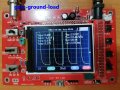
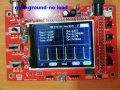
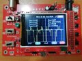
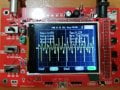
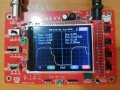
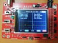
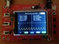
Pin 4 should not change with the load.
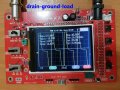
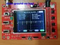
Pin 6 and the MOSFET drain will convey useful information both with and without the load.
Attachments
-
 213.1 KB Views: 10
 -
 210.6 KB Views: 10
 -
 171.7 KB Views: 10