Facebook
 Google
 GitHub
 Linkedin
Hello,
I think this is a very simple question but I am not an electronic/electrical major so was wondering if someone could help me out.
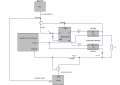
I am using a TTL (5V signal through a coaxial cable) from a function generator as a trigger to my microcontroller circuit (MSP430 Launchpad). In order to monitor the timing of the sequence, the TTL coax is split (using a coax T-piece) and with one connection going to the microcontroller while the other to an oscilloscope channel set to operate at 1 Mohm.
In order to prevent the pins from being damaged, I am passing the 5V TTL signal going to the microcontroller through a voltage divider to ensure that its pins are seeing only 3V (their operating voltage). As long as the voltage is above 3V, the microcontroller detects the pin state to be HIGH and is triggered to perform other functions.
This functioned well for a while, but suddenly from a couple of days, the TTL voltage that I am recording at the oscilloscope though starts with 5V, drops to about 0.8V after a couple of hours. Independently, the TTL when connected to the oscilloscope, is showing me a 5V signal. However, when I connect the remaining circuit at the T-piece, the voltage is immediately dropping to 0.8V on the scope and this is also not triggering the microcontroller (since it needs 3V). It makes me think that the circuit is drawing current but the microcontroller pins are configured to be INPUT which makes their input impedance extremely large (on the order of megaohms). So I dont quite understand the reason why the TTL voltage is dropping to 0.8V.
I was wondering if someone could kindly throw some light on why the TTL voltage is decreasing? Your advise will be truly appreciated.
Thank you.
P.S: Please see the circuit diagram attached.
I think this is a very simple question but I am not an electronic/electrical major so was wondering if someone could help me out.
I am using a TTL (5V signal through a coaxial cable) from a function generator as a trigger to my microcontroller circuit (MSP430 Launchpad). In order to monitor the timing of the sequence, the TTL coax is split (using a coax T-piece) and with one connection going to the microcontroller while the other to an oscilloscope channel set to operate at 1 Mohm.
In order to prevent the pins from being damaged, I am passing the 5V TTL signal going to the microcontroller through a voltage divider to ensure that its pins are seeing only 3V (their operating voltage). As long as the voltage is above 3V, the microcontroller detects the pin state to be HIGH and is triggered to perform other functions.
This functioned well for a while, but suddenly from a couple of days, the TTL voltage that I am recording at the oscilloscope though starts with 5V, drops to about 0.8V after a couple of hours. Independently, the TTL when connected to the oscilloscope, is showing me a 5V signal. However, when I connect the remaining circuit at the T-piece, the voltage is immediately dropping to 0.8V on the scope and this is also not triggering the microcontroller (since it needs 3V). It makes me think that the circuit is drawing current but the microcontroller pins are configured to be INPUT which makes their input impedance extremely large (on the order of megaohms). So I dont quite understand the reason why the TTL voltage is dropping to 0.8V.
I was wondering if someone could kindly throw some light on why the TTL voltage is decreasing? Your advise will be truly appreciated.
Thank you.
P.S: Please see the circuit diagram attached.
Last edited: