 Facebook
 Google
 GitHub
 Linkedin
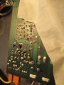
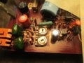
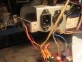
This is the circuit board for a Sankyo 702 projector I'm trying to fix. The reason for masking tape is so no one confuses amplifier section components for motor controller section. The 2 wire connector goes to the DC motor, the 3 wire connector goes to the main transistor on a heatsink, the blue wire and white wire are 36 volts AC input from transformer. This is a 2 speed projector and the 2 little trim pots fine tune each speed. Looks like 3 transistors on the board and 1 main transistor on the projector with a heatsink. I guess all the places where there is a capacitor and resistor in series is to prevent noise going to the audio section isn't it?
Attachments
-
 156.2 KB Views: 8
 -
 181 KB Views: 8
 -
 180.9 KB Views: 8
 -
 168.1 KB Views: 8


