 Facebook
 Google
 GitHub
 Linkedin
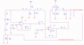
Hello - I'm trying to understand this circuit that drives a piezoelectric transformer to create high voltage AC at a sharp emitter point that generates positive and negative ions. At first glance I thought it was a Wien bridge oscillator followed by gain and a push-pull amplifier to drive the primary of the piezoelectric transformer. A closer look has left me confused. I don't understand why there is a capacitor (C5) between the output of the op-amp and the feedback and can't properly calculate that the phase delay at the frequency of oscillation (69 KHz) is 0 to cause oscillation. The gain created by R6, R5, and C4 is 3 at 69 KHz which is why I'm thinking that it is some form of a Wein bridge. The feedback is just high frequency pulses that occur when the AC voltage at the emitter point is very high positive or very high negative during corona discharge. Based on what I've found on the internet, the feedback for a wien bridge is normally meant to effect gain, but this is tied into the other part of the circuit?
I've never done a sinusoidal oscillator and haven't had to do much real analog design throughout my career so I'm struggling and would appreciate any advice to get me on a path to understanding this circuit. I'm trying to understand this circuit so that I have a shot of doing my own for a similar application. I have the hardware for this circuit, and have traced it several times and think the schematic is accurate. The circuit works, and oscillates with or without feedback.
Thanks for any help.
Attachments
-
 30.5 KB Views: 23


