Facebook
 Google
 GitHub
 Linkedin
Hi Guys
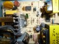
I have 3 receivers (bought 2 hoping hoping to fix the first), the same resistor has failed on all 3 receivers (the resistor ballooned 3 times it's size), replacing the resistor hasn't fixed the auto-reboot issue.
Any help would be appreciated.
Thanks in advance.
I have 3 receivers (bought 2 hoping hoping to fix the first), the same resistor has failed on all 3 receivers (the resistor ballooned 3 times it's size), replacing the resistor hasn't fixed the auto-reboot issue.
Any help would be appreciated.
Thanks in advance.