Troubleshooting Pioneer S-W700 subwoofer

MrChips

Joined Oct 2, 2009
30,810
Your aim is to get the brightness to be reduced.
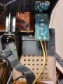
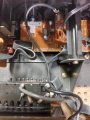
It would be helpful to see photos of the electronics. Let's begin with the power supply section.
It would nice to be able to make some resistance measurements (with power disconnected) at CN102/CN7101 and CN7502.


Pioneer S-W700 power supply.jpg

Edit: we're cross posting
 

MrChips

Joined Oct 2, 2009
30,810
Unplug the unit from mains power.

Look at connector CN7502.

Get a piece of hook up wire or a 100-1kΩ resistor and temporarily jumper across +B1 (pin-6) and REF.G (pin-10) to discharge the reservoir capacitors. Do the same for -B1 (pin-5) and REF.G (pin-10).

Measure the resistance between +B1 and REF.G. in both directions (i.e. reverse your meter connections).
Do the same between -B1 and REF.G.

(You can also use the wide solder tracks that are clearly labeled +B1 and -B1.)

Pioneer S-W700 CN7502.jpg
 

MrChips

Joined Oct 2, 2009
30,810
We can see that someone has already been at this unit and may have replaced the power transistors.
We will get to that in a minute.
 

Thread Starter

fordman76

Joined Mar 30, 2022
84
Didn't see this. I will do this tomorrow. I will perform those resistance measurements as well.

I sent you a pic of the power protec board where Q7514 and Q7512 are mounted. Looks like they have been fried. Looks like the driver transistors are suspect too. I have include some pics. Forgot to label what they are. I can send you the board layouts too if they would help.
 

Attachments

MrChips

Joined Oct 2, 2009
30,810
You have a LEFT CHANNEL and a RIGHT CHANNEL.
You will compare resistance measurements with the equivalent transistors in the two channels

LEFT === RIGHT
Q7511 --- Q7512
Q7513 --- Q7514

Measure resistance at each transistor in both directions (i.e. two measurements for each):
B-C
B-E
E-C
 

Thread Starter

fordman76

Joined Mar 30, 2022
84
Thank you. I will report my findings in the morning. I did the output transistor readings earlier, but did not indicate which transistor belongs to which channel. My bad.
 

Thread Starter

fordman76

Joined Mar 30, 2022
84
These are the measurements I got after discharging the caps: (jumper off)
B+ to Ground Ref. =0.40;
B+ to ground ref. =0.40 leads reversed
B- to ground ref. =0.20
B- to ground ref. =0.50 leads reversed

LEFT Channel
Q7511 (red lead on base) Q7511(leads reversed)
B-C=235.6 B-C=235.5
B-E=221.0 B-E=221.0
E-C=14.8 E-C=14.9

LEFT Channel
Q7513 (red lead on base) Q7513(leads reversed)
B-C=236.8 B-C=236.8
B-E=222.2 B-E=222.2
E-C=14.9 E-C=14.9

RIGHT Channel
Q7512 (red lead on base) Q7512(leads reversed)
B-C=0.6 B-C=0.6
B-E=0.6 B-E=0.7
E-C=0.4 E-C=0.5

RIGHT Channel
Q7514 (red lead on base) Q7514(leads reversed)
B-C=0.8 B-C=0.8
B-E=0.8 B-E=0.8
E-C=0.5 E-C=0.4

Looks like the right channel is the one that fried?
 

MrChips

Joined Oct 2, 2009
30,810
Ok. Remove the two transistors in the RIGHT CHANNEL, Q7512 and Q7514.

Repeat the +B1 and -B1 resistance measurements.

Then apply power and observe the brightness of the 100W test lamp.
 

Thread Starter

fordman76

Joined Mar 30, 2022
84
B1+ 1.56 m ohms black lead on B+ and red lead on ground ref.
B1+ 1.16 m ohms red lead on B+ and black lead on ground ref.

B1-1.76 m ohms black lead on B1- and red lead on ground ref.

B1-1.38 m ohms red lead on B1- and black lead on ground ref.

Brightness maybe slightly less but not much.
 

MrChips

Joined Oct 2, 2009
30,810
I would have liked to hear that the lamp had dimmed.
However, the testing continues.

With Q7512 and Q7514 removed, turn on power (with no speaker connected), volume level set to zero.
Measure the voltage with respect to GND at the all three pins of the four power transistors:

LEFT RIGHT
Q7511 Q7512
Q7513 Q5714

collector
base
emitter
 

Thread Starter

fordman76

Joined Mar 30, 2022
84
The right channel output transistors were NTE36 and NTE37. Are they good replacements for the 2SA1264N and 2SC3181N ? I am trying to find the spec sheets now just in case I have to order .
 

MrChips

Joined Oct 2, 2009
30,810
Responses:

Do not install Q7512 and Q7514.

No, you cannot use a CFL bulb. It must be incandescent.
Hence all the tests at this point are invalid.
 

MrChips

Joined Oct 2, 2009
30,810
And Q7512 and Q7514 B C E solder points (without the transistors installed)?

And the brightness of the 100W bulb?

Search for any transistors getting hot by finger test.
 

Thread Starter

fordman76

Joined Mar 30, 2022
84
100 watt incandescent bulb---voltage measured at solder joints backside of board.
Q7512 with
B = 6.34 v
C= 0.0 v
E= 6.30 v

Q5714
B = -5.51 v
C = 0.00 v
E= -.5.48 v

No transistors seemed hot on either board.
 
Top