 Facebook
 Google
 GitHub
 Linkedin
Guys,
I am trying to repair a 6 year old Weslo Cadence 21 treadmill.
The problem began with this treadmill having difficulty starting up. But for a few days, I could get it running my applying an initial manual push with my legs. Once started, it would keep working unless I left it alone and switched off for a few hours.
However, finally, it has stopped completely. The main DC traction motor refuses to start, whatever I do.
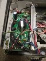
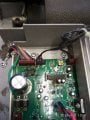
I took the cover off to discover that it has a U-MC2100E motor controller board. Using a multimeter, I can see the AC input to the board is fine. However, the DC voltage to the motor is always zero. The single LED on the board is lit up when power is supplied and stays a solid red without blinking. No signs of damage or leak on the main 400v / 560uf capacitor. Other components also look ok, visually and the console beeps happily when power is switched on.
Incline actuator works fine along with its cooling fan.
Pictures of the controller are attached
Could you please give me any indication on how I could go about troubleshooting the board and which specific electronic component(s) I should try replacing? Also, can the controller board be repaired at all or am I better off buying a new board? It is priced at £125 which makes me thing buying a new treadmill altogether may not be a bad idea
Any pointers would be most appreciated
I am trying to repair a 6 year old Weslo Cadence 21 treadmill.
The problem began with this treadmill having difficulty starting up. But for a few days, I could get it running my applying an initial manual push with my legs. Once started, it would keep working unless I left it alone and switched off for a few hours.
However, finally, it has stopped completely. The main DC traction motor refuses to start, whatever I do.
I took the cover off to discover that it has a U-MC2100E motor controller board. Using a multimeter, I can see the AC input to the board is fine. However, the DC voltage to the motor is always zero. The single LED on the board is lit up when power is supplied and stays a solid red without blinking. No signs of damage or leak on the main 400v / 560uf capacitor. Other components also look ok, visually and the console beeps happily when power is switched on.
Incline actuator works fine along with its cooling fan.
Pictures of the controller are attached
Could you please give me any indication on how I could go about troubleshooting the board and which specific electronic component(s) I should try replacing? Also, can the controller board be repaired at all or am I better off buying a new board? It is priced at £125 which makes me thing buying a new treadmill altogether may not be a bad idea
Any pointers would be most appreciated
Attachments
-
 205.1 KB Views: 149
 -
 219.2 KB Views: 138
 -
 112.3 KB Views: 118


