troubleshooting a tv power supply

Thread Starter

johndoe45

Joined Jan 30, 2010
364
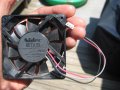
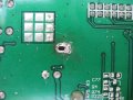
i got it finally. taking picture

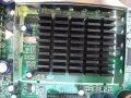
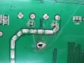
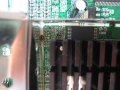
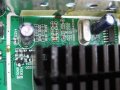
wondering if i did damage??????????? second and third picture. iron kept slipping when i tried to wiggle pieces out a little.

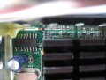
just desoldered two and bent the lid back
 

Attachments

Last edited:

R!f@@

Joined Apr 2, 2009
10,004
what the ? :eek:.
I NEVER expected that to be there. A heat sink fully shielded. Not here, never, I really donno what to say.
This changes a lot of things. Damn....OK
Get me a side way shot too, and find a small PC fan that can be fitted on top of that heat sink and show it to me.
I have to think this over.

First of all we need to keep that beast cool so we can trouble shoot with power applied.
second give me a shot from the other of that black LVDS connector next to the heat sink, I like to see where the tracks lead.

:ed
By the way you did fine for a beginner with that shield removal.
I have to admit, you are getting good
 
Last edited:

Thread Starter

johndoe45

Joined Jan 30, 2010
364
got a pc fan

i don't understand this?
from the other of that black LVDS connector next to the heat sink

and my brother didn't bring his camera. so will be using same one.
 

Attachments

Last edited:

R!f@@

Joined Apr 2, 2009
10,004
It's a 7V one.. then you will need a small regulator like 7805 to run it off from the supply 12V directly.
That fan has a tacho pin and I am assuming it to be the white one.. Correct me if I am wrong any one.
first see that you can run it by giving 5V to the red wire and black the ground wire, this Voltage will give u low noise and ambient air flow.
If the fan works, try to mount it on the heat sink, leave the shield out for now, use some silicon sealant at the sides, mount it in a way that are blows on to the sink and try not to obstruct the air flow in any way. It's OK if he fan touched the sink, from the looks of it a slight dab of silicon at the center of the fan and just placing it on the sink, after a slight pressure downwards will seep the silicon from the side and after a few hours it will be held in place quite nicely

Mount it securely from the sides, try not to block the side, so that I can flow out out. Leave it dry out and now you can make small regulator for it. U will need two 0.1uf 16V caps and 3 terminal regulator like LM7805. A piece of vero board to fix them a some long wires too.

Get the parts and I'll show you where to tap of the power to the regulator.

The Idea here is to keep the sink cool.
Since from the posts I can see that the shield heats up a bit and the result is TV does not work, may be the LSI chip under the sink is shutting down due to heat or for some other reason, which we are going to find out.
Keeping it cool will gives us time to measure voltages to see if the LVDS signal is being produced. The black connector is next to the sink and that chip is the only think we cannot see the no. Being the one heating up to an extent tells me this is the signal processor.
I really cannot understand what might have caused this, but to me it seems when you shorted out the supply, the surge together with static discharge could have caused some IO protection diodes to leak inside the chip. I cannot yet tell you that cooling will make the tv work since we now know that chip is heating up too much, indicating excessive power is consumed by the chip. But if the chip works when it is cool, then keeping it below the threshold temp will make it work for some time.
And during this time we can figure out if we can make it without the DSP replacement
 

R!f@@

Joined Apr 2, 2009
10,004
Hmm.. all good, but the regulator is a n adjustable, meaning resistor will be needed to adjust the out put
See that u get a standard 7805, it will easier a and then may be PCB won't be needed.
I'll show you an example on how to wire it with a pic using a 7805.
Then you'll have a better idea.
 

R!f@@

Joined Apr 2, 2009
10,004
Yup...
When can you get em.
Skip the vero board.
All we'll need is 7805, 2 caps, silicon and a screw to mount the reg on the chassis
 

Thread Starter

johndoe45

Joined Jan 30, 2010
364
alright. i got everything already. bought heat sink compound (silicone) unless want me to use one in my previous post.
so let me know what to do and i'll try to get it done tomorrow.

got a bunch of screws in garage
 

R!f@@

Joined Apr 2, 2009
10,004
I'll show u with in a few hours how to do it.
Oh dear. heat sink compound?
I don't remember saying that, I said silicon to mount the fan.
Heat sink compound in not necessary as the regulator won't heat up.
 

R!f@@

Joined Apr 2, 2009
10,004
U can do it like this and mount the regulator on to the chassis using a small screw.When mounting, find a place near the supply and use a short screw that does not go beyond the metal chassis, A long one may go down and break the panel or a tube inside, so be careful when choosing a screw for this. Learn and observe the area before mounting. Or find a hole that is far from the panel inside. If you in doubt post back.

The red should be connected to the 12V at the supply output. The yellow to the fan. The center are the GND's.
one GND to the supply, other to the fan.
Put a dab of silicon on the center of the fan and simply press on to the sink, air should flow on to the sink, downwards.
Once dried, fan will be held in place, u can test the fan by powering the TV.
Post back when done
 

Attachments

Last edited:

R!f@@

Joined Apr 2, 2009
10,004
Chassis is referred to any metal frame of the unit, which is normally grounded, or earthed.
Mount the regulator at the point shown, drill a hole if necessary.

The supply connections are as shown
 

Attachments

Last edited:

Thread Starter

johndoe45

Joined Jan 30, 2010
364
finally did everything you said. it is outputting 5 DCV at the wire going from the left regulator pin to the fan. but fan is not powering up. you said connect it to red cable of fan right?

how do i get a secure connection? do i have to cut the fan wires?

cause i just put wire in hole and not secure.

and the silicone is a sealant not an adhesive, so should i use heat sink compound or what? fan not sticking to heat sin
 
Last edited:

R!f@@

Joined Apr 2, 2009
10,004
If you are measuring 5V from the regulator then this part is done.
I hope you have mounted it to the metal chassis.

U have to cut the fan connector and join the wires. Leave the white wire. the black and red are the supply pins.
Red is the 5V and black is the GND ( fan wires).

The fan should work when you connect the two wires..
Before mounting fan, check it for operation.
If you can, show me your connection details.
 

Thread Starter

johndoe45

Joined Jan 30, 2010
364
well :confused: can i just take out a screw from metal chassis and put silicon on the regulator and rescrew the screw in?


and one quick question. I was wondering what was the purpose of the two 0.1 miicrofarad capacitors?
 
Top