Facebook
 Google
 GitHub
 Linkedin
my name is actually joseph.
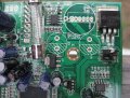
i will trace the track tomorrow. so should i remove the other capacitor? i think i'm going to buy a new solder gun tomorrow cause the tip on the one i have isn't very thin/narrow which leads to me having to be extremely careful of not burning the board. the Weller one that i am looking into that i posted earlier in these posts has like ten different tips.
yes i have no experience. this is the first time i'm even soldering and desoldering. i don't have an oscilloscope. i wish. those are like $300-1500 or something like that right?
what would an oscilloscope tell me anyway. thought it was more for design and testing capacitors, IC's and other SMD components. SMD components usually rarely go out in tv's anyway besides optoisolators and transistors, right???? the defective components in this thread were easy to identify requiring no use of a scope. and if wanted picture of my multimeter testing the bridge being shorted, should have told me earlier. threw it away already. i told step by step in post #90 http://forum.allaboutcircuits.com/showpost.php?p=225660&postcount=90 what i did to to test bridge and find that it was shorted
i'm majoring in mechanical engineering and thinking of minoring or even switching to electrical. probably minor though.
took physics II class but has no correlation to a real PCB. just a simple diagram with resistors, capacitors, and think that was it.
thanks Rifaa for helping me! this is extremely educational for me and the rest of the members of this forum.
Last edited: