Triangle wave 555 issues - tip not sharp enough

Thread Starter

hnhnhnhnhnhnh89

Joined Nov 23, 2022
11
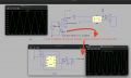
Hi, I'm a new electro student trying to figure out how to create a triangle wave with a 555 timer in LTSpice.
I need something that has an output of 6v (with the lowest point at 0v and peak at 6v), and that has a frequency of around 10khz.

The closest I get is with what I am attaching after some time of playing around with RC formulas. Unfortunately my triangle wave is just not sharp enough for my needs. Does anyone have any suggestions for what I could do to get a sharp triangle top, without any curves, while still maintaining the output requirements? The frequency does not have to be exact, but the sharpness and voltage output has to be fairly exact.

Many thanks for any suggestions.Screenshot 2022-11-24 at 12.38.56.pngScreenshot 2022-11-24 at 12.39.30.png
 

Attachments

Alec_t

Joined Sep 17, 2013
14,313
Welcome to AAC!
I don't think there's any way with just the 555 to get a sharp-peaked 6V amplitude when the power supply is only 6V.
An op-amp could be used to amplify a much smaller amplitude triangle wave from the 555. Or two op-amps could be used to make a hysteretic oscillator with a waveform very close to a decent triangle.
 

LowQCab

Joined Nov 6, 2012
4,064
Here's a simple way to get a virtually perfect Triangle-Wave .........
Power-Supply must be greater than ~12-Volts.
Any significant connected Output-Load will slightly alter the Frequency of Oscillation,
so the Circuit may require an Output-Buffer-Amp.
Also produces a Square-Wave at the same Frequency.
Can also be used with a Comparitor-Chip, as long as it's capable of ~20mA Output-Current.
.
.
.
Triangle Wave Generator  .png
 

MrChips

Joined Oct 2, 2009
30,795
The 555-timer circuit does not generate a triangular waveform.
For a triangular waveform output, use the square-wave and send it to an integrator circuit.

Ideal integrator
1669305189944.png


Practical integrator

1669305159521.png
 

crutschow

Joined Mar 14, 2008
34,412
I need something that has an output of 6v (with the lowest point at 0v and peak at 6v), and that has a frequency of around 10khz.
It's difficult to get a good 0-6V triangle wave with just a 6V supply.
You need a little higher supply voltage to allow some headroom.
Can you use a higher supply voltage?
 

crutschow

Joined Mar 14, 2008
34,412
Here's the Ltspice simulation of a triangular generator using two op amps similar to ronsimpson's, but has a virtual ground voltage (pgnd) to operate from a single supply.
It uses rail-rail type op amps, with U1 as an integrator to get close to 0V and 6V peak output (yellow trace).
The value of R2 determine the amplitude of the triangle output and can be tweaked to adjust that.
Pot U3 adjusts the frequency.

1669318734384.png
 
Last edited:

Thread Starter

hnhnhnhnhnhnh89

Joined Nov 23, 2022
11
WOW, super thanks for everyone's great suggestions and replies. I haven't hopped on a forum with this much engagement and support in a long time. It's very motivating given that I am completely new to this and only in my second term as an electro student.

I guess I should have provided the full story though. I have another circuit I have already made and right now I am just using a PWL signal to feed in a triangle wave into it. However, the circuit I attached above is eventually going to entirely replace "V2" in the file called PWNKRETS.asc.

This is not purely for simulation though. My entire class and I are working on an electro conversion on a Volvo XC90.
My task in the project is to design the circuit as shown in pwnkrets.asc and then solder 12 separate circuit boards, manually (one for each 12v battery). For now, I've been given the green light on my circuit board, provided it uses components to create the triangle wave and uses the right frequency.

Therefore, I am trying to find the simplest and least complex solution for creating a triangle wave and to essentially feed that into my main circuit to replace v2. If I can do that and make the "MYRIO" output look the same as it does in PWNKRETS.asc, then I'll have succeeded with my part of the project.

The course instructor has stated we are to use a 555 timer (not sure why), but I think the OP-amp options seem to be the best in any case and will argue for this instead.

I appreciate the info and feedback!!
 

Attachments

LowQCab

Joined Nov 6, 2012
4,064
You probably don't need a perfectly shaped Triangle-Wave.

Your "Scope" picture of the Wave You have now looks a little funky though.

What exactly does "V-1" do ?
Where does it come from ?
What are it's Specifications ?
Is that Circuit a supposed "simulation" of some other existing Signal ?,
( A Temperature/Pressure-Sensor, or maybe even a manual Pot ).

What does the "Pulse-Width-Modulated" (PWM) Signal control ?

The entire Circuit needs to be designed around a required Input/Output Response,
trying to design it one piece at a time is extremely difficult,
because all of the "sections" of the Circuit need to be compatible with each other.
.
.
.
 

Thread Starter

hnhnhnhnhnhnh89

Joined Nov 23, 2022
11
I'm quite aware of what he stated the problem was.
You don't need to shout.

The waveform he showed was filtered, so my question concerned whether the 555 timing wave (amplified to be near 0V and 6v) would be sufficient.

Yea, it seems it's not good enough.
If we compare the signal coming out of the MyRio branch, in the original file versus the one in v2 - its no longer a PWM.
It should look like this: Screenshot 2022-11-29 at 09.56.02.png
I cannot seem to figure it out. I think it may definitely be best to try and shoot in 12v into the 555 then and see if that does not fix the problem.
 

Attachments

Thread Starter

hnhnhnhnhnhnh89

Joined Nov 23, 2022
11
You probably don't need a perfectly shaped Triangle-Wave.

Your "Scope" picture of the Wave You have now looks a little funky though.

What exactly does "V-1" do ?
Where does it come from ?
What are it's Specifications ?
Is that Circuit a supposed "simulation" of some other existing Signal ?,
( A Temperature/Pressure-Sensor, or maybe even a manual Pot ).

What does the "Pulse-Width-Modulated" (PWM) Signal control ?

The entire Circuit needs to be designed around a required Input/Output Response,
trying to design it one piece at a time is extremely difficult,
because all of the "sections" of the Circuit need to be compatible with each other.
.
.
.
I gave it a try without the perfect shape and it doesn't seem right. You can see the difference by checking out the myrio signal in both files I just attached in the most recent post above this one (if you have a min that is).
 

Alec_t

Joined Sep 17, 2013
14,313
As has been said, you probably don't need a perfectly shaped triangle wave (for PWM control for your purpose).
For a perfect triangle wave, the width of each peak in the waveform varies linearly with height above base.
Now consider a very imperfect 'triangle' wave, as below:
triangle.jpg
Here's a plot of the positive-going peak widths (in microseconds) for each of the heights shown in blue:
Widths.jpg
As you can see, it's not quite a linear variation of width with height, but it's not far off and should be close enough for good PWM control in many applications, such as speed control.
 

Thread Starter

hnhnhnhnhnhnh89

Joined Nov 23, 2022
11
hi hn,
This is a cleaned up circuit version, is it OK for purpose.?
E
This is awesome!
I took your ideas and also some of the other suggestions regarding the 12 volt input.
In order to further simplify, I decided to make some adjustments, which I think work really well.
Afraid, I still needed the zener diode after the changes I made, but now I think this should be approved and I can get to ordering components and making 12 of these circuits for each lead acid battery. FINGERS crossed.
 

Attachments

Top