Facebook
 Google
 GitHub
 Linkedin
Hi,
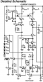
I'm trying to emulate the block diagram of the ICL8038 and can't figure out what the latch or flipflop should look like.
Two current sources charge and discharge a capacitor. The output of the flipflop should turn on and of the lower of the two current sources (Q3, Q4, R5). This is what I think needs to happen at the output:
How do I get that output for the given input?
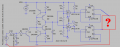
I'm trying to emulate the block diagram of the ICL8038 and can't figure out what the latch or flipflop should look like.
Two current sources charge and discharge a capacitor. The output of the flipflop should turn on and of the lower of the two current sources (Q3, Q4, R5). This is what I think needs to happen at the output:
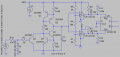
Code:
Comp U1     Comp U2   ->  Output
  0           0             1
  0           1             does not occur
  1           0             do not change output
1 1 0Attachments
-
 58.3 KB Views: 34


")