Facebook
 Google
 GitHub
 Linkedin
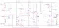
Hi i am new here, i need the circuit of a triangle wave generator without using op amp for homework and i can t find one, everyone uses op amp, is here someone who has the circuit schematic? I can only use R,C,bipolar tranzistor/t-mos,diode, zener diode, no L.
Triangle wave generator without using op amp
- Thread starter 10_catalin
- Start date