 Facebook
 Google
 GitHub
 Linkedin
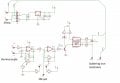
I have a schematic which uses a triac, for example a BT136. Please have a look at the attached schematic (this is a schematic for a soldering station)
What parameters from datasheet we should take into consideration when we are searching for a equivalent triac ? For example, if I will use BT138 instead of BT136, the soldering station will work correctly ? I searched the datasheet for both BT136 and BT138, and I saw that the gate trigger current for BT138 is highter that the gate trigger current of BT136. Meanwhile, in the MOC3041 datasheet it does not mention the maximum current, only the surge current. So I cant find if the BT138 is compatible with MOC3041. I am wondering if I can use BT138 as a substitute for BT136, in the uploaded schematic ?
Thanks in advance.
Attachments
-
 88.9 KB Views: 126


