Triac Equivalent - soldering station

Thread Starter

mike69

Joined Dec 22, 2012
83
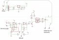
I saw a strange behavior at this soldering station (the schematic from the first post): while using LM358AN from ST and LM358N from Fairchild, the soldering station is working without any problems.
But when I am using LM358P from TI, a strange behavior starts to happen. When the triac turns on, the led is flickering for a very short time (about 1-2 seconds, after flickering the led goes on) and when the triac turns off the same behavior of the led (flickering) happens again and after flickering the led goes off.
Why this strange behavior of the led is happening ? It is normal ?
 
Last edited:

Thread Starter

mike69

Joined Dec 22, 2012
83
I built the soldering station and it seems to work correctly.
But I made a mistake when I draw the schematic. The 4.7M preset (multi turn) is wired reversed. I already built the PCB and I tested it, but I am wondering if this reversed preset could be a problem.
Please have a look at the following schematics: the "original schematic" is the original one, and "my schematic" is the schematic that I draw in Kicad.
I know that the direction of increasing the resistance changes, but I am wondering what other things can occur ?
It is a problem if I wired reversed the 4.7M preset ?
Will the soldering station work correctly ?
 

Attachments

Last edited:

Thread Starter

mike69

Joined Dec 22, 2012
83
I made R6 = 2.2Mohms and it seems to work. When R6 was 4.7Mohm I was having problems, the red led was flickering. But with 2.2Mohms it seems to work OK.
 
Last edited:

KeithWalker

Joined Jul 10, 2017
3,607
If the triac is connected backwards but everything else is the same, it will work correctly. Whether it will work if you connect the two resistors wrong will depend on how creative you are at choosing points in the circuit to connect them to.
 

ebeowulf17

Joined Aug 12, 2014
3,307
I have another question regarding this project (the attached schematic).
What are the consequences if the triac is connected backwards or if the two 220R resistors are connected wrong ?
Depends on what you mean by "connected backwards."

Are you talking about inserting the TRIAC into its PCB holes backwards, such that pins 1 & 3 trade places? If so, it definitely will not work normally.

If you're talking about drawing the schematic and laying out the board differently, there might be more than one right answer, but certain relationships must be maintained.
 

Thread Starter

mike69

Joined Dec 22, 2012
83
I am talking about changing pins 1 and 2. So I am talking about changing pin 1 with pin 2 and pin 2 with pin 1 of the triac
Also I am talking about if pin 3 is connected to pin 6 of MOC3041 instead of pin 4.
Also, If the triac is connected from pin 2 of triac to pin 4 of MOC instead of pin 6 of MOC and pin 1 of triac is connected to pin 6 of MOC instead of pin 4 of MOC.
I am interested to know the consequences of the above mentioned mistakes.
 

KeithWalker

Joined Jul 10, 2017
3,607
I am talking about changing pins 1 and 2. So I am talking about changing pin 1 with pin 2 and pin 2 with pin 1 of the triac
Also I am talking about if pin 3 is connected to pin 6 of MOC3041 instead of pin 4.
Also, If the triac is connected from pin 2 of triac to pin 4 of MOC instead of pin 6 of MOC and pin 1 of triac is connected to pin 6 of MOC instead of pin 4 of MOC.
I am interested to know the consequences of the above mentioned mistakes.
What do you think will happen in each of these cases?
 

Thread Starter

mike69

Joined Dec 22, 2012
83
1. I made a mistake at the beginning and I swapped by mistake pin 1 and 2 and the triac was always on.
2. I don't know, but probably it would not work correctly.
3. Probably it would not work correctly. I don't know for sure.
 

ebeowulf17

Joined Aug 12, 2014
3,307
I am talking about changing pins 1 and 2. So I am talking about changing pin 1 with pin 2 and pin 2 with pin 1 of the triac
Also I am talking about if pin 3 is connected to pin 6 of MOC3041 instead of pin 4.
Also, If the triac is connected from pin 2 of triac to pin 4 of MOC instead of pin 6 of MOC and pin 1 of triac is connected to pin 6 of MOC instead of pin 4 of MOC.
I am interested to know the consequences of the above mentioned mistakes.
Wow, that's a lot of questions! The consequences of each swap depend upon which other connections you drag along for the ride when you swap things. TRIACs are well suited for switching AC - they don't care which direction current is flowing through them, so reversing TRIAC 1/2 or Opto 4/6 doesn't matter, as long as the proper relationship is maintained between the TRIAC gate and its other two terminals.

[EDIT. I've snipped a couple paragraphs where l described polarities wrong.]

If you're not planning to change components, but only plan to re-arrange them, then feel free to swap connections top/bottom (as shown on schematic) as long as you maintain the correct gate/T1/T2 relationships.
 
Last edited:

Dodgydave

Joined Jun 22, 2012
11,395
Wow, that's a lot of questions! The consequences of each swap depend upon which other connections you drag along for the ride when you swap things. TRIACs are well suited for switching AC - they don't care which direction current is flowing through them, so reversing TRIAC 1/2 or Opto 4/6 doesn't matter, as long as the proper relationship is maintained between the TRIAC gate and its other two terminals.

When you want the TRIAC to be off you need the gate to be held at the same voltage as T2 (also known as MT2 or A2, depending on whose datasheets you're looking at.) So there should be a resistor directly between gate and T2, with no switches of any kind in between. This ensures that the TRIAC is always off except when you want it on.

When you want the TRIAC to be on, you need the gate voltage to be different from T2 by enough to cause current to flow through T2 and the gate. The typical way to do this is by switching in a connection between T1 and gate. This current flow is what turns the TRIAC on, although once it's on, current flow through T1 and T2 keeps the TRIAC on until current stops flowing, even if you break the gate connection.

In reality there are a LOT of ways to get TRIACs switching, some better than others. If you're not planning to change components, but only plan to re-arrange them, then feel free to swap connections top/bottom (as shown on schematic) as long as you maintain the gate/T1/T2 relationships.

The Triac turns on when the gate and MT2 are the same polarity, there is usually a resistor between MT1 and Gate.

With a 4 Quadrant Triac, the Gate can be fired Negative wrt MT2, and vice-versa.

To test a Triac, short Gate and MT2 together.
 

ebeowulf17

Joined Aug 12, 2014
3,307
The Triac turns on when the gate and MT2 are the same polarity, there is usually a resistor between MT1 and Gate.

With a 4 Quadrant Triac, the Gate can be fired Negative wrt MT2, and vice-versa.

To test a Triac, short Gate and MT2 together.
Arghhh! Did I get that backwards? Sorry everybody, I'll edit my previous post to trim the errors.
 

Thread Starter

mike69

Joined Dec 22, 2012
83
Hello,
I am using a Gordak soldering iron (24V and 48W) for the soldering station from the attached schematic.
I found that the soldering iron may have a leakage current through the ceramic heating element when the temperature rises above a limit.
What are the consequences of the leaky heating element ?
There is a connection from the tip of the soldering iron to the ground of the 230V receptacle, that is not shown in the schematic.

1. Can the leaky heating element affect negatively the soldering iron ?
2. Can the leaky heating element affect negatively the soldering station ?
3. Can the leaky heating element affect negatively the component that is being soldered on the pcb ?
 

Attachments

KeithWalker

Joined Jul 10, 2017
3,607
Hello,
I am using a Gordak soldering iron (24V and 48W) for the soldering station from the attached schematic.
I found that the soldering iron may have a leakage current through the ceramic heating element when the temperature rises above a limit.
What are the consequences of the leaky heating element ?
There is a connection from the tip of the soldering iron to the ground of the 230V receptacle, that is not shown in the schematic.

1. Can the leaky heating element affect negatively the soldering iron ?
2. Can the leaky heating element affect negatively the soldering station ?
3. Can the leaky heating element affect negatively the component that is being soldered on the pcb ?
If the heating element is leaking to ground, the answers to your questions are:
1. Yes
2. Yes.
3. No, as long as there is a good ground connection to the soldering iron tip and your circuit board is on a grounded anti-static mat.
 

KeithWalker

Joined Jul 10, 2017
3,607
Can you please explain what could happen in those above situations ?
Is the circuit ground shown in your diagram is connected to the power ground, as it should be? If it is, a short to ground on the heating element could draw too much current and burn out the element or overload the circuit.
 

Thread Starter

mike69

Joined Dec 22, 2012
83
The ground of the soldering station, which is connected at the rectifier ground (rectifier minus) is not connected to the mains (power) ground.
 
Top