 Facebook
 Google
 GitHub
 Linkedin
Hello,
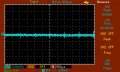
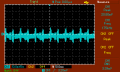
I built the attached schematic and I wanted to find if the TL431 oscillates, using an oscilloscope.
I tested by connecting the ground probe to the 220uF capacitor ground and the detachable hook to TL431 catode.
The measurements were made when the soldering iron was connected into the circuit.
1. Can you please explain if there are oscillations in the screenshots ?
2. It is normal to be multiple sine waves in the same screenshot, as it is in MAP002 and MAP003 ?
Attachments
-
 2.4 KB Views: 7
 -
 3 KB Views: 9
 -
 2.5 KB Views: 8
 -
 2.4 KB Views: 7
 -
 2.8 KB Views: 7
 -
357.1 KB Views: 11


