 Facebook
 Google
 GitHub
 Linkedin
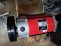
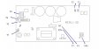
I have this motor controller and the motor as well.
In pictures.
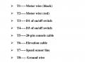
I see the DC output to the motor T1/T2
I see the AC input T3/T4
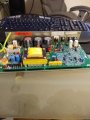
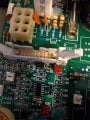
And I see VR1. I assume this to be a potentiometer. If this control the speed of the motor or if it is some preset thing.
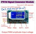
And I see the T5, the 20 pin ribbon connector. I assume that it is some of those pins that perhaps is related to PWM that gets the motor going. How to identify those 20 pins, 10 on each row. If any of the pins relates to PWM, which ones? . If all I have to do is get a PWM, a picture included.
My question is becoming obvoius. How can I get the motor going given what you see.
In pictures.
I see the DC output to the motor T1/T2
I see the AC input T3/T4
And I see VR1. I assume this to be a potentiometer. If this control the speed of the motor or if it is some preset thing.
And I see the T5, the 20 pin ribbon connector. I assume that it is some of those pins that perhaps is related to PWM that gets the motor going. How to identify those 20 pins, 10 on each row. If any of the pins relates to PWM, which ones? . If all I have to do is get a PWM, a picture included.
My question is becoming obvoius. How can I get the motor going given what you see.
Attachments
-
 3.2 MB Views: 32
 -
 161.1 KB Views: 33
 -
 831.5 KB Views: 33
 -
 50.9 KB Views: 34
 -
 59.9 KB Views: 31
 -
 116 KB Views: 31


")


