Facebook
 Google
 GitHub
 Linkedin
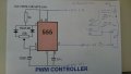
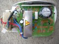
I have a problem with the named board, it is a board that activates a DC motor from a range of 0V to 180V. The board consists of a double power supply / transformer, which delivers 10v and 17v continuously, the whole is transformed into a square wave for the operation of the motor at those high voltages. The problem arose after the first dc motor died, my girlfriend despite having told him not to turn on the treadmill anymore she thinking that by staying still for a week she would come to life only went to turn it on again, result?10A fuse break after a large spark. I reset the fuse and going to check the output gives me a voltage of 330V always ... I have the impression that the component that is in metal depicted in the photo is dead. This component is drowned in a resin and protected by a metal sheet (which I have already removed). .. can anybody help me? ? I also accept help to build a suitable controller, because you get paid including the card for a non-screen printed and therefore unrecognizable component.
I have attached the controller pcb pic and schematics.
I have attached the controller pcb pic and schematics.
Attachments
-
 1.1 MB Views: 256
 -
 86.9 KB Views: 273

") )
)