Treadmill motor control

Thread Starter

jz_aac

Joined Sep 2, 2023
10
I have a Pacemaster Proselect treadmill which recently stopped working with error code 11. Was told that the keypad membrane was the issue, but no longer available. After searching online, found https://ctmprojectsblog.wordpress.com/2018/09/29/treadmill-dc-motor-mc-60-controller/, and decided to follow suit. Since I am entirely a novice in electronics, even following suit has been challenging.

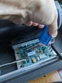
My initial trial has been on speed control (I entirely left out the incline motor aspects). The motor on my treadmill only has two sets of wires going in (see motor 1). One set is for DC power (2 wires, red and black), the other one (3 wires, red/white/black) connects to the control board where the label is "Strobe". Since MC-60 MCB does not have a corresponding place, I left out the "Strobe" wire from the motor.

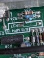
After connecting everything onto MC-60 (AC wires from power cord; DC wires to motor; control wires from potentiometer), I plugged the power cord into the wall. Only 2 out of 4 red lights on MC-60 were lit (see MCB 3). I was not able to make the motor run by adjusting the potentiometer. The two lights that were off, one is labeled as "SCR TRIG", the other "CUR LIM" (again, I am not sure; they are nearby).

I assume leaving out "Strobe" wires was the cause. Is this the case? How do I incorporate it into MC-60? If not possible, how do I leave it out correctly? Thanks a bunch!

J

motor 1.jpgMCB 3.jpg
 

MaxHeadRoom

Joined Jul 18, 2013
30,654
The MC-60 does not use a strobe type RPM control but features a feedback loop internally.
Normally all the MC-60 needs to run is power, the two motor leads and a 5k pot. ?
Assuming your are by-passing the console and just running off the Pot?
 

Thread Starter

jz_aac

Joined Sep 2, 2023
10
It was a 5k pot. Yes, I am by-passing the console and running off the pot.

The MC-60 was purchased from Ebay. What is the best way to test the board with a multimeter? Thank you!
 

Thread Starter

jz_aac

Joined Sep 2, 2023
10
Thanks.

I found this document (MC-60modcollection.pdf) from one of your posts. Regarding LED D6, it says:
"D6- Labeled SCR. Indicates that the SCR is triggering on the controller. If this light is out, no voltage will be sent to the motor. Note that this LED will vary in brightness, depending on the speed setting. If this LED does not light when the safety key is inserted and D7 is lit (indicating a speed setting other than zero MPH), the controller will need to be replaced."

I rechecked the board while plugged in. The voltage from the potentiometer varied between 0 to 12V depending on dial position. There was no DC power (V = 0 between A+ and A-) to the motor. I think the controller I received is defective.
 

Thread Starter

jz_aac

Joined Sep 2, 2023
10
Just received another MC-60 through Ebay. This one worked. Motor speed can now be controlled.

To make the motor run smoother/quieter, I plan to put a 1500 uF/200V capacitor in between the DC motor out terminals of the MC-60. Since there is no dedicated place for the capacitor on the board, what will such a connection typically look like? How do I secure the body of the capacitor?

Also, I noticed that R37 on the board was disconnected at one end. Is this intentional?

Thank you!
 

Attachments

Thread Starter

jz_aac

Joined Sep 2, 2023
10
I have not yet found a suitable choke. So I went ahead with the 1500 uF capacitor and a 1M ohm bleeder. The treadmill ran a lot smoother than without the capacitor. But when I stepped onto the treadmill, it immediately became louder. After a few seconds, the fuse (Snap action MB1) on the power cord popped.

I didn't test the treadmill underload before I added the capacitor into the circuit, so I don't know if this was caused by the way I added the capacitor. What issue in the MC-60 itself could cause this symptom?

Thank you!
 

MaxHeadRoom

Joined Jul 18, 2013
30,654
As in my previous post regarding fitting a large capacitor to this type of control, i.e., Triac bridge, it is generally omitted on purpose.
Especially with this design where the RPM feedback is obtained from the DC power output side.
 

Thread Starter

jz_aac

Joined Sep 2, 2023
10
Thank you! I will continue looking for a choke. I will also disconnect the capacitor to see whether the treadmill, other than running not that smooth, could handle load normally.
 

Thread Starter

jz_aac

Joined Sep 2, 2023
10
Finally was able to get a choke ( P/N 130993 ) from Ebay. After adding it in series with the motor, the treadmill worked reasonably well.

When I walked/ran on it, there was a noticeable change of pitch with each step. The noise was not unbearable; it was just noticeable. I can't really say for sure that the treadmill was much quieter than this before the keypad membrane went out. I guess I want to know whether there are other things I can do to the MC60 to make the treadmill quieter.

In terms of safety switch, should I just use an on/off switch, or is it possible to incorporate magnetic key/reed switch? How difficult is the latter? Thanks!
 

Thread Starter

jz_aac

Joined Sep 2, 2023
10
Thank you!

The original upper control board has the reed switch on it (lower left corner). I can try to reuse this (and the magnetic key setup). How do I make sure that this reed switch is rated for 15A? Or should I purchase one with known rating?upper board.jpg
 

MaxHeadRoom

Joined Jul 18, 2013
30,654
Are you sure about the 15a rating required? If it is so, you probably would need a relay operated by the simple magnetic reed switch for that current.
 

Thread Starter

jz_aac

Joined Sep 2, 2023
10
I am not sure. But my wiring is very similar to shown below (credit: ctmprojectsblog), so I assume it is 15A.

If a relay is needed, where can I find a schematic for such a setup? Thank you!mc-60-control-treadmill-dc-motor-wiring1c.jpg
 

Thread Starter

jz_aac

Joined Sep 2, 2023
10
The reed switch is part of the original upper control board, which was controlled through the keypad on the dash. As far as I know, the upper control board and the lower control board on the treadmill worked fine. It was the keypad membrane which stopped working, and is no longer supplied. That was the reason I chose MC60 to replace the lower control board, and bypass the upper control board all together.

For the safety switch, I was thinking of using the reed switch mentioned above, only as a part, if it can be built into my current setup easily. I don't have the knowledge to figure out how to use the circuit it was involved in the upper board. Can you give a pointer or 2 on the relay you mentioned?

Thank you!
 

MaxHeadRoom

Joined Jul 18, 2013
30,654
First, you would need to do a little reverse engineering of the present set up, I am not familiar with that board so it would have to be known to go much further.
 
Top