Treadmill MC 60 Motor Controller not working.

Thread Starter

hsohpaul

Joined Jan 5, 2018
9
Hello Everyone

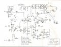
Just need some help in fixing MC 60 Controller board. I am making a pitching machine and took out this board and DC motor out of a treadmill.
My machine was running for a while but yesterday somehow I shorted two resistors (ground wire was touching these resistors). As soon as it shorted, motor started to run at max speed. I unplugged it and found out one end of two resistors popped out ( Resistor R-37 and Resistor RPS 2). I soldered them but couldn't get the motor going again.

Attaching a picture of MC motor controller board.

All LEDs come on when plugged in except Current Limit.
Can somebody explain what else might go wrong?? it would be much appreciated.

Thanks
 

Attachments

MaxHeadRoom

Joined Jul 18, 2013
28,696
So is it not running at all or still full tilt?
Have you checked the SCR bridge components?
R37 is often lifted as it is a rpm option and should not affect the running,
Max.
.
 

Thread Starter

hsohpaul

Joined Jan 5, 2018
9
So is it not running at all or still full tilt?
Have you checked the SCR bridge components?
R37 is often lifted as it is a rpm option and should not affect the running,
Max.
.
Hey max

Thanks for replying

Yes motor doesnt run at all. Checked the voltage across the terminal its 1 vdc max. Pot is working fine (Checked it with multimeter ).

LED scr trig always stays on. Is it suppose to be on?

How can I check 2 SCRs (S4020L)? Can I check it on circuit board or do I need to take it out of the board??
Sorry I am not experienced with electronics ..
 

MaxHeadRoom

Joined Jul 18, 2013
28,696
In the bridge, you have two rectifiers and two SCR's, it could be any one or more shot.
The one across the bridge, D12 rarely, if ever goes.
You may have to remove them and test with a meter.
Max.
 

Thread Starter

hsohpaul

Joined Jan 5, 2018
9
2 s
In the bridge, you have two rectifiers and two SCR's, it could be any one or more shot.
The one across the bridge, D12 rarely, if ever goes.
You may have to remove them and test with a meter.
Max.
Thanks Max. Ill do that today and will let you know.
 

Thread Starter

hsohpaul

Joined Jan 5, 2018
9
In the bridge, you have two rectifiers and two SCR's, it could be any one or more shot.
The one across the bridge, D12 rarely, if ever goes.
You may have to remove them and test with a meter.
Max.
So I tested all three rectifier and 2 SCRs and they all are in good condition.
Anything else I can check??
Should I check the opto coupler??
 

MaxHeadRoom

Joined Jul 18, 2013
28,696
Some have reported the opto failing, do you have the schematic? There are previous posts of it here in reverse-engineered format.
Max.
 

Thread Starter

hsohpaul

Joined Jan 5, 2018
9
Some have reported the opto failing, do you have the schematic? There are previous posts of it here in reverse-engineered format.
Max.
Yeah I was followng those threads. I found these schematic that matches my MC 60 board.
Optocoupler in my board is MOC 3052 as per these schematics. In case if its the culprit, can I replace it with MOC 3042 as this was the only one available in our local electronics shop?
 

Attachments

MaxHeadRoom

Joined Jul 18, 2013
28,696
IIRC the MOC3042 is a zero crossing opto, the MOC3052 is random phase type, which you will need, see the Fairchild AN-3006 for the types.
Max.
 

MaxHeadRoom

Joined Jul 18, 2013
28,696
Advisable to test using a lamp in place of the motor, If you jumper the output of the Opto 4 to 6 you should turn the bridge on full if it does not output then you should be able to trace where the power section of the circuit with a meter, observe that some points will be AC only etc.
Max.
 

Thread Starter

hsohpaul

Joined Jan 5, 2018
9
Advisable to test using a lamp in place of the motor, If you jumper the output of the Opto 4 to 6 you should turn the bridge on full if it does not output then you should be able to trace where the power section of the circuit with a meter, observe that some points will be AC only etc.
Max.
Hey max

I am getting around 95 vdc (on multimeter) while putting a jumper between 4 and 6. Does it mean there is something wrong with the circled part??
 

Attachments

Top