Transistors

MrChips

Joined Oct 2, 2009
34,814
It doesn't matter if there is one or two supplies.

The point is, the base current has to come from somewhere. It doesn't matter where the base supply is referenced.

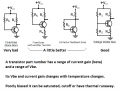
For educational illustration, it is common to show the base current coming from a separate voltage source.
In most circuit applications, the base current is supplied by some node in the circuit. There is not usually a separate supply to provide the base current.
 

Thread Starter

anditechnovire

Joined Dec 24, 2019
105
fig 2 is not practical but very interesting. There isn’t much advantage to doing it that way. You can achieve the same with proper biasing resistors. The reason why it’s not practical is that you really need two sources to achieve with one reversed. The load is between the 2nd source and ground being switched with full voltage at base. The negative bias on load causes base to bias lower and achieve higher current through the base which in turn achieves more current through collector... again only really works in saturation and no practical use plus very difficult to achieve with one source and circuits just are not designed that way because it’s more practical to have on source and ground. Also you have to throw out almost all the way to calculate transistors done that way. Looks interesting in simulation.
I think am really misunderstanding the concept of a transistor circuit, with two power supply, and one with one power supply, (self bias) where the base share the collector voltage. I don't think In will control collector current any longer in a self bais mode. Am I right ?
 

Thread Starter

anditechnovire

Joined Dec 24, 2019
105
The AC signals are analog audio or video. The emitter follower provides a high input impedance and a low output impedance.
The voltage divider biases the base at a calculated voltage so that an analog input can cause the output swing to be the maximum it can be.
The input and output capacitors block the DC but pass the AC.
If you have a DC input signal then the emitter output voltage is a diode voltage drop less than the input voltage.
In this case, is the transistor operated in self bias, (base sharing collector voltage vcc) or is the base current coming from the ac signal, then the voltage divider limit the amount of the input ac signal, so that the amplified signal be maximum.
Am not sure of what am saying.
 

MrChips

Joined Oct 2, 2009
34,814
Stop using the term "self bias".

The base bias comes from a source provide by the circuit. Do not be fixated with where is this bias source.

In an audio amplifier, the objective is to amplify the audio signal which is AC.
The base of the transistor is given a signal AC + DC, where AC is the audio signal and DC is the bias.

The purpose of the DC bias is to get the transistor in the proper operating range.
If you would like to learn more about transistor load line and DC operating Q-point we can take you there.


1578521759439.png
 

Wolframore

Joined Jan 21, 2019
2,619
Exactly to get a transistor amplifier to operate at its quiescent point in the middle of the load line, you must bias the base correctly. This isn’t done with 2 different batteries or DC sources. Your AC signal is a whole different thing, now affected by impedance and can be decoupled from the DC aspects to achieve amplification without issues of saturation or cutoff.

Self bias is a concept generally used for JFETs and depletion MOSFETS.
 

Janis59

Joined Aug 21, 2017
1,894
Why is the input mode different in some" CC "mode? Some are between the E-B while others are between the B-C
Simplest answer: because the Vcc and Gnd FOR AC is absolutely and definitively the one and the same thing. If equivelent impedance between both wires is more than miliohms, this circuit never will work anyway. That is reason why filter capacitor is applied between Vcc and Gnd.
 

atferrari

Joined Jan 6, 2004
5,012
Not to extend the discussion about the expression "self bias" but it is what I heard the first time I was explained polarization, with a resistive divider. And, yes, it is clear that one or two sources where the voltage/s come from, makes no difference in how I perceive it.
 
Last edited:

MrChips

Joined Oct 2, 2009
34,814
You could add another perspective to "self bias" using "emitter bias".

Emitter bias.jpg
If VEE is at the correct negative voltage the bias can be arranged so that the base is at 0V, i.e. no DC bias required.
 

MisterBill2

Joined Jan 23, 2018
27,522
Why is the input mode different in some" common collector "mode of a transistor circuit diagram? Some are between the emitter-base while others are between the collector- base. Will they not have different effects?
The fact is that there are indeed quite a few different kinds of circuits and they certainly do have different characteristics. And there is no promise that a simulator will be able to provide an accurate representation of how they will actually work.
 

Thread Starter

anditechnovire

Joined Dec 24, 2019
105
Stop using the term "self bias".

The base bias comes from a source provide by the circuit. Do not be fixated with where is this bias source.

In an audio amplifier, the objective is to amplify the audio signal which is AC.
The base of the transistor is given a signal AC + DC, where AC is the audio signal and DC is the bias.

The purpose of the DC bias is to get the transistor in the proper operating range.
If you would like to learn more about transistor load line and DC operating Q-point we can take you there.


View attachment 196457
Pls what does this audio or video ac signal really does to the base of the transistor and capacitor, and how it affects the output signal either at the base or at the collector
 

Wolframore

Joined Jan 21, 2019
2,619
ohh this is a can of worms... you are asking very complex questions, so let's discuss it in steps... DC bias is completely different from AC response where we need to consider miller capacitance and the effect of phase relationships which is affected by the frequency of the signal where we need to consider jωt as affected by the RC response of the transistor/circuitry. If we looked at it in a very basic way capacitors couple AC while blocking DC. In actual circuit it's not that simple. We need a good foundation to go there.
 

crutschow

Joined Mar 14, 2008
38,508
Pls what does this audio or video ac signal really does to the base of the transistor and capacitor, and how it affects the output signal either at the base or at the collector
At the middle of the design frequency range, the capacitor values are normally selected such that they have no significant effect on the AC signal and pass it without change (the capacitors do block any DC voltage).
The signal does cause the base bias current to increase and decrease slightly, generating an AC current change (equal to the input change times the Beta current-gain) in the collector bias current.
This appears as a change in voltage across the collector load impedance, giving a (usually) amplified version of the AC input signal.

Make sense?
 

Thread Starter

anditechnovire

Joined Dec 24, 2019
105
Y
At the middle of the design frequency range, the capacitor values are normally selected such that they have no significant effect on the AC signal and pass it without change (the capacitors do block any DC voltage).
The signal does cause the base bias current to increase and decrease slightly, generating an AC current change (equal to the input change times the Beta current-gain) in the collector bias current.
This appears as a change in voltage across the collector load impedance, giving a (usually) amplified version of the AC input signal.

Make sense?
Yeah really thanks, but what do u mean by the statements"The signal does cause the base bias current to increase and decrease slightly"
 
Top