Transistor...?

Audioguru

Joined Dec 20, 2007
11,248
If you use negative feedback from the collector to the base then the input impedance becomes low.
But if you use negative feedback with an unbypassed emitter resistor then the input impedance becomes high.

The emitter resistor reduces the differences of Vbe of different transistors and the differences of hFE. If unbypassed, the emitter resistor reduces the AC voltage gain, reduces distortion and increases bandwidth.

I can't remember and don't care if it is called series or shunt or voltage or current feedback.
 

Thread Starter

RRITESH KAKKAR

Joined Jun 29, 2010
2,829
If you use negative feedback from the collector to the base then the input impedance becomes low.
But if you use negative feedback with an unbypassed emitter resistor then the input impedance becomes high
.
how.....??
 

Audioguru

Joined Dec 20, 2007
11,248
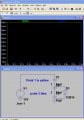
The 8 ohm load directly shorts the collector of the transistor to ground. It needs an output coupling capacitor between the collector and the 8 ohm load. Then the collector will have its normal average DC voltage of about +5.8V.

Your transistor has a 2k ohms collector resistor. It works pretty well when its capacitor-coupled load is 20k ohms and more. But the 8 ohm load shorts its AC output to ground.

Don't you know that the voltage gain of a single common-emitter transistor is the collector resistor value in parallel with the load resistance divided by the unbypassed emitter resistance? Then your total collector resistance is only 7.97 ohms and the total emitter resistance is about 409 ohms so the voltage gain (loss) is 7.97/409= 0.02 times.

A power amplifier uses a complementary emitter-followers output stage to deliver high current with a very low output impedance (as I have told you in many of your other threads) to the low impedance speaker.

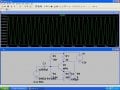
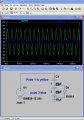
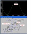
In your simulation, the input has a peak AC voltage of only 5mV (0.005V). If the transistor has no load then its voltage gain is only Rc/Re= 2k/409= 4.89 times so the output will have a peak AC voltage of only 5mV x 4.89= 24.5mV (0.0245V).

You need to learn about simple basic arithmatic in addition to simple basic electronics.
 

Thread Starter

RRITESH KAKKAR

Joined Jun 29, 2010
2,829
In your simulation, the input has a peak AC voltage of only 5mV (0.005V). If the transistor has no load then its voltage gain is only Rc/Re= 2k/409= 4.89 times so the output will have a peak AC voltage of only 5mV x 4.89= 24.5mV (0.0245V).
sir, as you have taken Gain Rc/Re, i think it is used when there is not coupling capacitor at emitter but, when we use a capacitor there come something like re.
 

Audioguru

Joined Dec 20, 2007
11,248
sir, as you have taken Gain Rc/Re, i think it is used when there is not coupling capacitor at emitter but, when we use a capacitor there come something like re.
An emitter resistor bypass capacitor is not called an emitter coupling capacitor.

Your circuit does not have an emitter resistor bypass capacitor so the total emitter resistance is the 400 ohm resistor plus the 9 ohms transistor internal emitter resistance.
 

Thread Starter

RRITESH KAKKAR

Joined Jun 29, 2010
2,829
I have assemble single transistor amplifier on PCB, with 12V Vcc and I/P coupling capacitor with 10Uf, the biasing was correct as i stimulate it in LT Spice.

When i connect speaker Between collector and ground it does not sound. the input signal was taken from my DTH stb(audio lead).

Pls tell what is the problem is the signal feed is small or....??
 

edgetrigger

Joined Dec 19, 2010
133
I asked you to do the analysis. You have continently used LT spice, and even on that the schematic is wrong. This is a very elementary circuit and if you can’t analyse this then how can you design anything else. If you really want to design circuits you got to put in effort, slog to decipher.
 

Thread Starter

RRITESH KAKKAR

Joined Jun 29, 2010
2,829
I asked you to do the analysis. You have continently used LT spice, and even on that the schematic is wrong. This is a very elementary circuit and if you can’t analyse this then how can you design anything else. If you really want to design circuits you got to put in effort, slog to decipher.
Ok, now you tell your question and answer of it.
Thank's
 

Audioguru

Joined Dec 20, 2007
11,248
Where is the transistor amplifier? I see just 3 capacitors and a diode instead.

A single transistor cannot drive a low impedance speaker because its voltage gain is Rc (the speaker in parallel with the collector resistor) divided by Re (the emitter resistance plus emitter resistor). It doesn't have enough current to drive a speaker.

3 transistors make an extremely simple power amplifier to drive a low impedance speaker. The first transistor has voltage gain and it drives a complementary pair (NPN plus PNP) of emitter followers like this:
 

Attachments

Thread Starter

RRITESH KAKKAR

Joined Jun 29, 2010
2,829
I don't understand it why diode are used ,Why voltage divider biasing is not used.
& How to now the output level of signal, as in LT spice we give value but in actual,How to measure??:D
 

Attachments

Audioguru

Joined Dec 20, 2007
11,248
I don't understand it why diode are used, why voltage divider biasing is not used?
Maybe your teacher should teach that a silicon diode has a forward bias voltage that is almost exacly the same as the base-emitter junction (a silicon diode) of a transistor. Both are affected by temperature change the same so they cancel the effect of temperature change.
If you use a voltage divider made with two resistors then as the transistors heat, their current increases which makes them heat more which makes their current increase more which makes them heat more which makes their current increase more which makes them heat more which makes their current increase more which makes them heat more which makes their current increase more which .....
Do you understand that this is called "thermal runaway"?
Usually the diodes touch the transistors or their heatsinks for good thermal coupling.
A transistor can replace the two diodes.

How to know the output level of signal, as in LT spice we give value but in actual, How to measure??:D
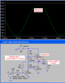
It is difficult to see the output level in a Simulation program because a transistor has distortion that compresses the waveform.
In a circuit you use an AC milli-voltmeter to measure audio levels. A multimeter is accurate only at low mains frequencies (50Hz and 60Hz).
 

marshallf3

Joined Jul 26, 2010
2,358
I don't understand it why diode are used ,Why voltage divider biasing is not used.
& How to now the output level of signal, as in LT spice we give value but in actual,How to measure??:D
Interesting amp circuit but I've seen a ton that were better. Of course while most of us would just use an IC for a simple audio amp nowadays you do need to learn all of this.
 

Audioguru

Joined Dec 20, 2007
11,248
In my circuit, R1 is for negative feedback and provides base bias current for Q1.

Use simple arithmatic to calculate a suitable value for R2.
R2 is the collector load resistor for Q1 and it provides base current for Q2.
Q2 creates a peak voltage of 2.5V in the 8 ohm speaker so its current is 2.5V/8= 313mA. The emitter voltage of Q2 peaks at +6.75V and with a current of 313mA its VBE is 0.85V so the base voltage peaks at +7.6V. The supply is 9V so R2 has 1.4V across it therefore its current is 1.4V/680= 2.1mA. The collector current is 313mA - 2.1mA= 310.9mA and the base current is 2.1mA so its hfe is 148.

The hfe could be as low as half so the value of R2 should be reduced.
If R2 is bootstrapped then the open-loop gain is higher, the distortion is reduced and the output can swing higher which produces more output power.
Look at Bootstrapping in Google or ask your teacher.
 

Thread Starter

RRITESH KAKKAR

Joined Jun 29, 2010
2,829
Look at Bootstrapping in Google or ask your teacher.
I know Bootstrapping, it is for increasing I/P impedance by resistance and capacitor from output.
your were saying for replacement of diode, a transistor can be used pls. tell, how??
 
Top