Facebook
 Google
 GitHub
 Linkedin

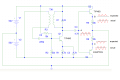
I am having trouble with a project and I was wondering if anyone here could help. It is pretty straight forward so I would assume that someone has run into this problem before. I have attached a schematic of the circuit with related info. As an overview, the object of the project is to drive an inductive load of about 10 Ohms at a frequency around 900 kHz with a peak current of 1.8 amps. The schematic has the two parts finished so far. To the left is an armstrong oscillator which provides the correct frequency. It provides the necessary voltage as measured and displayed at voltage point A. This part works. To the right, the voltage is sent to two complimentary transistors to create a class-b (push-pull) amplifier. The voltage is sufficient, but I need to amplify the current. The load is not shown. The two 10k resistors are placed between the transistors while I test to make sure that the transistors are switching properly (before I actually start letting sizeable current flow through). Now here is the problem: The transistors are not shutting off. It seems to defy everything that a transistor should do. The oscilloscope readings are shown at points B and C, the expected reading and the actual reading.
The maximum peak voltage at point A is around 40V. Now I thought that this might be the problem, but by messing around with the oscillator I was able to reduce this to a mere 2V peak to test this and still the transistors did not shut off.
The frequency is fairly high and I thought that maybe capacitance was an issue. The transition frequency of the transistors is 10 MHz which should be sufficient, but to test this idea I reduced the freqency of the oscillator to 60 kHz and there was no change.
I thought that maybe the transistors were bad, so I replaced them and also with other types of transistors, some that didn't even have the proper frequency response. While the voltage at B and C was significantly reduced with the wrong transistors, the transistors still did not shut off.
Then I thought that I would put some diodes after point A to rectify the current before it even got to the transistors. Because of the frequency and voltage I used high power shottky diodes. The diodes DID NOT rectify the current at all!
This is not my first project. In the past I have been able to shut off a transistor and have been able to rectify with a diode. What is it about this circuit that causes all the components to defy the laws of physics?
The maximum peak voltage at point A is around 40V. Now I thought that this might be the problem, but by messing around with the oscillator I was able to reduce this to a mere 2V peak to test this and still the transistors did not shut off.
The frequency is fairly high and I thought that maybe capacitance was an issue. The transition frequency of the transistors is 10 MHz which should be sufficient, but to test this idea I reduced the freqency of the oscillator to 60 kHz and there was no change.
I thought that maybe the transistors were bad, so I replaced them and also with other types of transistors, some that didn't even have the proper frequency response. While the voltage at B and C was significantly reduced with the wrong transistors, the transistors still did not shut off.
Then I thought that I would put some diodes after point A to rectify the current before it even got to the transistors. Because of the frequency and voltage I used high power shottky diodes. The diodes DID NOT rectify the current at all!
This is not my first project. In the past I have been able to shut off a transistor and have been able to rectify with a diode. What is it about this circuit that causes all the components to defy the laws of physics?
Attachments
-
 42.7 KB Views: 168


 Are you sure the transistors are wired correctly?