Transistor that has TWO emitters & Servo amp

Status
Not open for further replies.

Thread Starter

DexterMccoy

Joined Feb 19, 2014
429
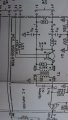
What is this type of transistor called, and what kind of circuit's is it used in and for?

The Transistors have a X crossing in the Servo amplifier, what does this X crossing do?
 

Thread Starter

DexterMccoy

Joined Feb 19, 2014
429
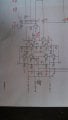
This transistor has Two Emitters, look at the schematic

What is it called and what kind of circuits is it used for and why does it have 2 emitters?
 

shteii01

Joined Feb 19, 2010
4,644
That is not X crossing. There is no big black dot in the middle of the X.

What you have is two wires that run from emitter of one transistor to the base of another transistor. The two wires are not connected to each other.
 

Papabravo

Joined Feb 24, 2006
22,113
But why the 2 emitters? what does having 2 emitters do? why not 2 bases? or 2 collectors?
Well an emitter will source current. So in a logic gate, if both emitters are high, there is no current flow from collector to either emitter and the transistor is off. This allows the collector to be pulled high.

In logic terms "A high AND a high is a high"

If either of the emitters is pulled low then the transistor is on and the collector is pulled low as well.
 

Thread Starter

DexterMccoy

Joined Feb 19, 2014
429
So why do they want to "choose" the pins that source current than to sink current?

They aren't using the multiple emitter transistor as an ampilifer

They are using the multiple emitter transistor as a Switch? so choosing sourcing current or sinking current shouldn't be a problem right? they could hook the signals to any pins of the transistor because it's used as a switch
 

Thread Starter

DexterMccoy

Joined Feb 19, 2014
429
The two wires don't actually connect in the middle, so the current from one wire DOES NOT enter the other wire.
Yes I know that, I'm not asking about that

The X crossing pattern is a push pull arrangement?

Because Q25 goes to Q29 WHY?
Why does Q26 goes to Q28?

Is this some type of push pull arrangement or what?
 

ifixit

Joined Nov 20, 2008
652
The circuit is an H bridge motor driver. The two sides of the "H" must work in an opposite manner with respect to each other... hence the crossover connection.
 

Papabravo

Joined Feb 24, 2006
22,113
The purpose of an H bridge is to steer the current through the motor coil in both directions. In one of the directions the motor moves in the clockwise direction, and in the other direction it moves counter clockwise. A uni-directional servo motor is only useful for producing a controlled velocity. For position control it is like a WOM (Write Only Memory)
 
Status
Not open for further replies.
Top