Transistor switching 3.3v with 12v logic

Thread Starter

ethanwhite

Joined Jun 13, 2013
6
Hi, I like electronics but I'm no guru :)

I've been trying to find a way to switch the 3.3vdc GPIO logic of my Raspberry Pi (which I got from school) when I have 12vdc present.

My project is to record the state of the 12v logic from an alarm system (see image below)



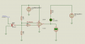
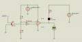
I originally thought a relay would be a good idea however I've since been reading on transistors and the transistor way seems better. I designed a circuit first with the idea that the base of the transistor would allow me to switch C and E but I'm getting more than 3.3v (which would blow up my raspberry pi) and I really don't want to do that...



Where did I go wrong :( the LED is just acting as a diode, I know it's the wrong way round. 12v is acting as one of the trigger outputs.

Ideally I'd like it so when I get a +12v the raspberry pi sees a +3.3v.
 

wayneh

Joined Sep 9, 2010
18,183
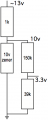
You could use a zener diode to cap the output voltage, for example at 10V, and then divide that down with 2 resistors. (You'll need a 3rd resistor to limit current through the zener.)

I still don't understand where your voltage of 8.55V was measured. Does the Pi share common ground with the other two voltage sources?

One problem with your diagram is an LED on a 3.3V circuit. Some LEDs will not light with that low voltage, so the voltage at the collector of the transistor is sort of unpredictable.
 

Papabravo

Joined Feb 24, 2006
22,113
Use a comparator powered from 12V. It has an open collector output that can be pulled up to 3.3V. A quad part is the LM339 and the dual is LM393. Set the reference input to about 6V (for example) and you input goes to the other input. The output can be inverted by swapping the + and - inputs to the comparator. A series resistor on the input will protect against excessive currents.
 

Thread Starter

ethanwhite

Joined Jun 13, 2013
6
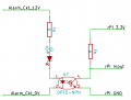
it was measured on the wire below where it says 3.3v. The software sucks so I've drawn a diagram below

http://i.imgur.com/Jb00lEd.jpg

It shouldn't say 8.55v though, it should say 3.3v and I don't know why unless it's because the ground is shared?

On the new diagram I'm unsure if I should be sharing the ground on the E side of the transistor (dotted line).
 

Thread Starter

ethanwhite

Joined Jun 13, 2013
6
Use a comparator powered from 12V. It has an open collector output that can be pulled up to 3.3V. A quad part is the LM339 and the dual is LM393. Set the reference input to about 6V (for example) and you input goes to the other input. The output can be inverted by swapping the + and - inputs to the comparator. A series resistor on the input will protect against excessive currents.
Thanks I've never seen a comparator before, have I understood correctly? I have a new diagram:

http://i.imgur.com/PF5MxAk.jpg

So I have a reference voltage for my raspberry pi on gpio 12 to solve the problem of a floating pin when it comes to programming, and a 3.3v into the comparator. When +12v is < 3.3v I should see a 3.3v from the output into gpio 6.
 
Last edited:

wayneh

Joined Sep 9, 2010
18,183
any simulation or pcb design package will have schematic capture.
Yeah, my problem is I had years of experience with drawing programs. Freehand was my favorite by far but Adobe bought it to kill it years ago. I have zero experience with any circuit software. So it's like Eric Clapton laying down his guitar to learn the tuba. Kinda tough.
 

Thread Starter

ethanwhite

Joined Jun 13, 2013
6
Thanks for the info, if the optoisolator is an npn transistor controlled by an LED how do I know if I'm controlling the LED correctly? is it just:

Resistance = (12v - LED req voltage) / Forward continuous current

Maplins has a YY63T but I don't know what the LED's required voltage is. Peak reverse voltage? http://www.ebay.co.uk/itm/320894141740
 

wayneh

Joined Sep 9, 2010
18,183
Yes, that's pretty much it. You generally want to stay well below the rated current of any LED though, to extend its life. You just need enough light to make the coupling work reliably, and that may be only 20mA if it's rated for 30. The manufacturer should be able to supply more detailed specifications to help you make such a judgment.
 

Thread Starter

ethanwhite

Joined Jun 13, 2013
6
looks like the YY63T is a ILD74 (which is why I couldn't find any info). Is the Forward voltage part what I should be looking at in the data sheet? So using a 12v supply, and a 1.3v @ 20ma is 560 ohms resistance.

Am I on the right lines?
 

Papabravo

Joined Feb 24, 2006
22,113
looks like the YY63T is a ILD74 (which is why I couldn't find any info). Is the Forward voltage part what I should be looking at in the data sheet? So using a 12v supply, and a 1.3v @ 20ma is 560 ohms resistance.

Am I on the right lines?
Reread the secion of the b-book that talks about open-collector and open-drain outputs. It is a very useful piece of knowledge. Remember that such outputs can be wire-ore'd together.
 
Top