Facebook
 Google
 GitHub
 Linkedin

Hi, I like electronics but I'm no guru 
I've been trying to find a way to switch the 3.3vdc GPIO logic of my Raspberry Pi (which I got from school) when I have 12vdc present.
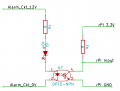
My project is to record the state of the 12v logic from an alarm system (see image below)

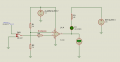
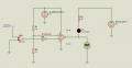
I originally thought a relay would be a good idea however I've since been reading on transistors and the transistor way seems better. I designed a circuit first with the idea that the base of the transistor would allow me to switch C and E but I'm getting more than 3.3v (which would blow up my raspberry pi) and I really don't want to do that...

Where did I go wrong the LED is just acting as a diode, I know it's the wrong way round. 12v is acting as one of the trigger outputs.
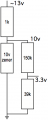
Ideally I'd like it so when I get a +12v the raspberry pi sees a +3.3v.
I've been trying to find a way to switch the 3.3vdc GPIO logic of my Raspberry Pi (which I got from school) when I have 12vdc present.
My project is to record the state of the 12v logic from an alarm system (see image below)
I originally thought a relay would be a good idea however I've since been reading on transistors and the transistor way seems better. I designed a circuit first with the idea that the base of the transistor would allow me to switch C and E but I'm getting more than 3.3v (which would blow up my raspberry pi) and I really don't want to do that...
Where did I go wrong
the LED is just acting as a diode, I know it's the wrong way round. 12v is acting as one of the trigger outputs.Ideally I'd like it so when I get a +12v the raspberry pi sees a +3.3v.