Transistor ouptut stage

Thread Starter

Zeeus

Joined Apr 17, 2019
616
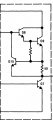
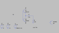
Hi..Trying to understand transistors

Without input signal,
If Q2 is pnp then the left side of C1 is about 0v

but if Q2 is npn it is about -12V (vee), please why?

Is this correct? :
If it is about -12V then little or no current through Q2 but alot of current through Q1...Made this circuit on breadboard and almost immediately, "ALOT" of smoke...due to power dissipation on Q1? (Q1 burnt) but it burnt only after applying input signal

With input signal and npn and pnp possible to get close full swing with dc quiescent of left side of C1 at 0v..but how to do same with npn and npn?

Thanks
 

Attachments

Audioguru

Joined Dec 20, 2007
11,248
Your circuit will not do anything because the bases of the transistors do not have a DC reference voltage, they are floating all over the place. The bases also have no signal, V3. V3 has a DC reference voltage of 0V and a signal with a peak voltage of 6V.

With V3 connected to the bases and the NPN wrong transistor as Q2 then there will be no output signal and both transistors will blow up because they will both be turned on conducting a very high current.
With V3 connected to the bases and the PNP transistor used for Q2 then there will be an output sinewave with crossover distortion.

Q1 is an emitter-follower. If its base DC reference voltage is 0V then the input signal on its base can cause its emitter to swing up to almost +12V and down to almost -12V.
If Q2 is a PNP then it is also an emitter-follower and its emitter can also swing up to almost +12V and down to almost -12V. Then both transistors can provide plenty of output current to a load.

But if Q2 is an NPN it CANNOT have a base voltage of 0V and an emitter voltage of -12V because its maximum base-emitter voltage is the 0.7V of its forward-biased base-emitter diode.
 

Thread Starter

Zeeus

Joined Apr 17, 2019
616
But if Q2 is an NPN it CANNOT have a base voltage of 0V and an emitter voltage of -12V because its maximum base-emitter voltage is the 0.7V of its forward-biased base-emitter diode.
Please how?

and thanks, maybe can limit current

Edit : By limiting the current like this, will there be smoke? but output swing is low 3vpp
 

Attachments

Last edited:

AnalogKid

Joined Aug 1, 2013
12,126
By limiting the current like this, will there be smoke?
The current limit function will not work as shown.

Your question is so unclear that evaluating your circuit is difficult. However, my GUESS is that you want Q4 to limit the current through Q1. If so, the collector of Q4 should be connected to the base of Q1, not Vcc. It's job is to shunt current around the base-emitter junction.

Also, without any base current limiting you definitely will make smoke. V3 will overcurrent the Q2 base-emitter junction trying to pump 1000 amps into Vee.

ak
 

Thread Starter

Zeeus

Joined Apr 17, 2019
616
The current limit function will not work as shown.

Your question is so unclear that evaluating your circuit is difficult. However, my GUESS is that you want Q4 to limit the current through Q1. If so, the collector of Q4 should be connected to the base of Q1, not Vcc. It's job is to shunt current around the base-emitter junction.

Also, without any base current limiting you definitely will make smoke. V3 will overcurrent the Q2 base-emitter junction trying to pump 1000 amps into Vee.

ak
Thanks but if change the collector of Q4 to base of Q1 : base of Q1 is input signal

and yeah yeah...emitter of Q2..Thanks

ka
 

AnalogKid

Joined Aug 1, 2013
12,126
Thanks but if change the collector of Q4 to base of Q1 : base of Q1 is input signal
Correct. The idea behind this type of current limiting is to divert current from the input *away* from the base. This works ***only*** if there is a resistor in series with the base.

ak
 

Thread Starter

Zeeus

Joined Apr 17, 2019
616
Correct. The idea behind this type of current limiting is to divert current from the input *away* from the base. This works ***only*** if there is a resistor in series with the base.

ak
speaking about directing current away from base

is this an example?

Can the collector of this circuit be biased to be at 1/2 Vcc ?
expecting this circuit to have gain of R1/R3 as looks like inverter op amp
 

Attachments

Audioguru

Joined Dec 20, 2007
11,248
Why don't you want a simple symmetrical circuit that uses a complementary pair of NPN and PNP transistors like most audio amplifiers and opamps use?
 

AnalogKid

Joined Aug 1, 2013
12,126
speaking about directing current away from base, is this an example?
No. The input current, and some of the collector load current, goes into the base.
Can the collector of this circuit be biased to be at 1/2 Vcc ?
Yes, but the bias point is not stable with temperature.
expecting this circuit to have gain of R1/R3 as looks like inverter op amp
Close, but not exactly. The forward gain of the circuit is related to R1 / R3, but the actual equation is more complex because the R1-R2 node is not a zero-ohm impedance point.

ak
 

Audioguru

Joined Dec 20, 2007
11,248
The LM381 was a preamp IC but it is obsolete now. They used all NPN output stage because in those days maybe they could not make a good PNP output transistor on an IC.
 
Top