This thread went all over the place and I wanted to be sure since the suggestions being posted were using relays and I want to eliminate the relays from my project.
A JFET (not a standard FET or MOSFET - try a J112 for size) will pass maximum current with zero gate bias; use negative voltage to turn it off. They're very handy get-out-of-jail-free cards for circuits where turnon is passive and turnoff is active.
This thread went all over the place and I wanted to be sure since the suggestions being posted were using relays and I want to eliminate the relays from my project.
This thread went all over the place and I wanted to be sure since the suggestions being posted were using relays and I want to eliminate the relays from my project.
Well, if that's the case, the circuit that Sgt. Wookie gave you is perfect! The relay that he shows in his circuit (connected to the Drain) would be your OEM relay.
On the other hand, some circuits in automobiles have the +12V side hard wired to the device, including relays. The circuit is powered by swiching the neg terminal to GND. If that's the case then the N Channel FET schematic that I posted should work. In that case, the relay that I show would be your OEM relay.
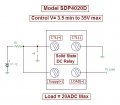
Yes, your post was overlooked somehow. Anyway, I don't think they make normally closed solid state relays (that I know of) but Dano can wire the SSR in this link like this.. http://www.mpja.com/prodinfo.asp?number=17288+RL
Ah, that's why (if I'm not certain) I always say "That I know of". An old Canadian expression ...CYA.
BTW, the little SSRs that you posted would be much better suited for what Dano needs to drive than the 20A monster that I posted. I had drawn that schematic prior to realizing that Dano only wanted to drive OEM relays.
Excellent ideas. Keep 'em coming!
I had a duh moment.
I never thought to look for a NC solid state relay.
The $20 cost might be prohibitive for this little project, but that was a great idea.
I'll do more digging.
Thanks everyone for being patient with an amateur.
Just check the current draw on the OEM relays that you're going to control to make sure that they don't exceed the rating of the SSRs. Doubtful though.

 Facebook
 Google
 GitHub
 Linkedin