Facebook
 Google
 GitHub
 Linkedin
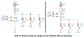
Whatever. Adjust the resistance values to suit your taste.With your pot set at max output voltage, the unloaded voltage divider produces only 5V/3= 1.67V and the LEDs get less than 1V each. Whte leds at less than 1V produce no light.
Transistor LED dimmer
- Thread starter william.in.rs
- Start date