I did in post #6.
Again for the third time speaking only about the dissipation on the transistor.
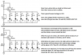
Compare these two circuits. The linear is suppling 50 ma constant and the PWM is suppling 49.5ma average
Apologize to william.in.rs for getting off track here.
That is not the definition of efficiency. I never claimed that they both dissipated the same power in the transistor.
The PWM circuit is supplying twice the current half time and thus supplying the same light. The power drawn from the battery is identical, so the same output at the same power means the same efficiency.
As is always the case, that is not the whole story. Typical LEDs are less efficient at higher current. So the PWM method, in a real circuit is actually likely less efficient.
But the load includes the series resistor, so the power dissipation is just transferred from the transistor to the resistor, thus no significant improvement in overall efficiency.
(Note, that if you increase the peak current for PWM operation, the resistor dissipation increases with the square of the current.)
If you are speaking about the total circuit. I wasn't. The transistor dissipates less wattage or heat using PWM therefore it's operating in a more efficient mode. What's wrong with that?
Somebody should start a new thread "Linear mode vs PWM mode LED dimmer" and continue discussion there.
Can anybody answer my questions:
1. What should be values of resistors R16 and R18?
2. Are Q3 and Q4 really PNP transistors?
3. Is 200 mW minimum dissipation for Q3?
Your are correct and I apologize.
How can anybody answer your questions when the schematic in post #1 is a guess?
What is the model number of the camera?
Can anyone explain why these circuits posted have the load on emitter instead of the collector ? And what would differ if the load is instead, on the collector ?
Can anyone explain why these circuits posted have the load on emitter instead of the collector ? And what would differ if the load is instead, on the collector ?
Load on the collector (common emitter configuration) provides voltage gain.
Load on the emitter (common collector configuration) provides current gain. We want to control the output current to the LEDs and don't care about voltage gain.
It also has built-in negative feedback. If the current tries to increase, the base drive is decreased thus keeping the LED current constant.
With your pot set at max output voltage, the unloaded voltage divider produces only 5V/3= 1.67V and the LEDs get less than 1V each. Whte leds at less than 1V produce no light.
 Facebook
 Google
 GitHub
 Linkedin