Facebook
 Google
 GitHub
 Linkedin
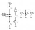
Could this circuit be a LED dimmer?
Can anybody suggest values for R16 and R18 to dim 6 white 5mm LEDs D1..D6?
Can anybody suggest values for R16 and R18 to dim 6 white 5mm LEDs D1..D6?
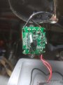
Attachments
-
 31.3 KB Views: 61

")