Facebook
 Google
 GitHub
 Linkedin
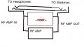
I have a schematic attached of a fm antenna booster and I tried the bias shown as a test with a transistor and the transistor's output is about 1/10 of a volt from collector to ground. I am powering it with three volts and when I add a 10K resistor from the base of the transistor to ground I found that I was able to achieve 1/2 the supply voltage of 3V which was about 1.4V at the collector to ground. I used a 560 ohm resistor from collector to positive instead of 1K since the circuit call for 12V and I want to use 3V. With the circuit as it is, I think the 27K base bias resistor is too low and it has to be much higher because the output is about 1/10 of a volt measured from collector to ground. If and when I assemble the whole circuit as shown in the schematic, would R1 alone of 27K overload the transistor and prevent RF amplification of the FM signal? Is the bias wrong as shown with only R1 and I should use the 10K from base to ground? The output voltage should be at 1/2 the supply voltage of quiescent right? I want to build the circuit to boost the fm antenna signal for my Walkman via the headphone jack connection since the headphone wire is used as an fm antenna. I think I know how to isolate the amplified signal using RF chokes and capacitors.
Attachments
-
 29.4 KB Views: 15