Ok so I'm closer but still have a couple of holes in my understanding for calculating each piece correctly.
I see your diagram for bright led is using 5V to the led just as I am but it's using 3.3V for the transistor base. I'm going through and attempting to calculate all of my values using 5V for both.
The diagram says to calculate R1 using the voltage (my case would be 5V), 2mA which is right for me, being 1/10th of the collector current (20mA), and 0.7V?
Where does 0.7V Come from? Voltage drop after the resistor or is this related to the resistor? I can't find any values related to my resistor of .7V.
Calculating R2, it says that the current-imiting resistor has 1.7V across it. How do we calculate that with ohms law? I'm 1.8V/20mA and getting .09 so I don't see how that translates... Maybe I have a problem with conversions.
The base-emitter of a transistor is a silicon diode. its voltage is about 0.7V when it is turned on. The datasheet for a 2N3904 transistor shows that it is 0.8V when a saturated transistor has 20mA collector current so I was a little off. I am attaching the graph from the datasheet.
The base resistor has 5V on one end and 0.8V on the other end so it has 4.2V across it. Then its value should be 4.2V/2mA= 2.1k but 2.2k is fine.
Calculating R2, it says that the current-limiting resistor has 1.7V across it. How do we calculate that with ohms law? I'm 1.8V/20mA and getting .09 so I don't see how that translates... Maybe I have a problem with conversions.
20mA is 0.02 Amps. Then the calculation is 1.7V/0.02= 85 ohms. Use 82 ohms. You calculated 0.09k ohms which is 90 ohms.
You used 100 ohms so your collector and LED current is 1.7V/100 ohms= 17mA which looks like the same brightness as 20mA.
For voltage after R1, I would do I = 5V/2.5K Ohms = 2V ?
The transistor base-emitter diode sets its base voltage at 0.7V to 0.8V.
The 2.5k base resistor does not have 5V across it, instead it has 5V - 0.8V= 4.2V across it. You were calculating its current which is 4.2V/2.5k= 1.68mA.
2.5k is not a standard resistor value but 2.2k is a standard value and will produce a base current of 4.2V/2.2k= 1.9mA which is fine.
The base-emitter of a transistor is a silicon diode. its voltage is about 0.7V when it is turned on. The datasheet for a 2N3904 transistor shows that it is 0.8V when a saturated transistor has 20mA collector current so I was a little off. I am attaching the graph from the datasheet.
The base resistor has 5V on one end and 0.8V on the other end so it has 4.2V across it. Then its value should be 4.2V/2mA= 2.1k but 2.2k is fine.
20mA is 0.02 Amps. Then the calculation is 1.7V/0.02= 85 ohms. Use 82 ohms. You calculated 0.09k ohms which is 90 ohms.
You used 100 ohms so your collector and LED current is 1.7V/100 ohms= 17mA which looks like the same brightness as 20mA.
The transistor base-emitter diode sets its base voltage at 0.7V to 0.8V.
The 2.5k base resistor does not have 5V across it, instead it has 5V - 0.8V= 4.2V across it. You were calculating its current which is 4.2V/2.5k= 1.68mA.
2.5k is not a standard resistor value but 2.2k is a standard value and will produce a base current of 4.2V/2.2k= 1.9mA which is fine.
Great, I see .8V now! Also realize I should have been using the voltage difference calculated from the voltage coming into the resistor and the desired voltage after the resistor. We already know 2mA is whats needed. Perfect.
The book I picked up actually explained this very well. I read into the formulas a little more closely as it wasn't clear everywhere I saw it on line... I did the calculations with the 100Ohm resistor and see what you mean. That should work just fine.
And cool, got it. Voltage difference again.
Thanks again for taking the time to help answer my questions! It is greatly appreciated!! Speaks very highly of your community... I'm sure I'll have other questions before too long but I feel I've gained a great deal of knowledge pretty quickly to get me on my way. I'm going to redo my 4x4x4 and make sure I have the right values there and everything is turned the right way :-o and then move on to making it standalone with the atmega16. I found some led cube software written in C so i'm excited to start playing with that...
Yes there is a bit for a serial interface although I haven't completed it. You can check the link I posted above to see the schematics for it and how the interface is used. It allows you to control it directly from the computer which is kinda cool.
To load data to it from the PC, I built a programmer for the atmega16 and plug the programmer directly into the slot you see on the board.
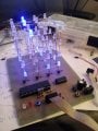
Almost done constructing the 8x8x8 cube itself, then I'll be onto the controller. For the 8x8x8 it's quite a bit more complex so we'll see how it goes!

 Facebook
 Google
 GitHub
 Linkedin






 .