Facebook
 Google
 GitHub
 Linkedin

I have a 12 VDC actuator. The actuators direction is controlled by reversing the polarity in the two leads connected to the actuator. I want to tap into each of these two leads and connect a transistor, to use as a switch, to control an input into a micro processor. When power is applied to the actuator to move in direction X, I want the transistor to act like a closed switch, being closed for the duration power is applied to the actuator. This will ground the input into the processor, bringing it low. I will do this by connecting the base of the transistor to +12V from the actuator, connected via a suitable resistor. The Emitter will be connected to the actuator wire that is grounded. When power is applied to the actuator to move in direction Y, I dont want anything to be done by the transistor, except act like an open switch, therefore leaving the processor input high.
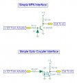
At first I didnt think I need to worry about reverse polarity at the transistor. On a breadboard however, I was getting unexpected current entering/leaving the Collector with the Base was grounded and the Emitter connected to +12VDC. I thought if the polarity of the transistor was reversed, no current would flow into/out of the Collector. I tried connecting a diode upstream of the Base (Option A in sketch), but still measured a small current, 0.3mA, entering/leaving the Collector when the polarity was reversed. Connecting a diode downstream of the Emitter (Option B) seemed to solve the problem. I understand the Option B will drop an additional 0.7V, but I am not worried about that for this application. Or I dont think I need to be worried about this, as all I am using the transistor for is to pull a processor input low.
Three questions:
(1) I would appreciate it if someone could shed some light on why a current is flowing to/from the Collector in Option A when the polarity was reversed.
(2) do I need to worry about reverse polarity protection here?
(3) is Option B the best way providing polarity protection here, given the Emitter could be either connected to +12V or ground, depending upon the power supplied to the actuator and that I do not want to use a diode in parallel with a fuse.
Thank you.
JG
At first I didnt think I need to worry about reverse polarity at the transistor. On a breadboard however, I was getting unexpected current entering/leaving the Collector with the Base was grounded and the Emitter connected to +12VDC. I thought if the polarity of the transistor was reversed, no current would flow into/out of the Collector. I tried connecting a diode upstream of the Base (Option A in sketch), but still measured a small current, 0.3mA, entering/leaving the Collector when the polarity was reversed. Connecting a diode downstream of the Emitter (Option B) seemed to solve the problem. I understand the Option B will drop an additional 0.7V, but I am not worried about that for this application. Or I dont think I need to be worried about this, as all I am using the transistor for is to pull a processor input low.
Three questions:
(1) I would appreciate it if someone could shed some light on why a current is flowing to/from the Collector in Option A when the polarity was reversed.
(2) do I need to worry about reverse polarity protection here?
(3) is Option B the best way providing polarity protection here, given the Emitter could be either connected to +12V or ground, depending upon the power supplied to the actuator and that I do not want to use a diode in parallel with a fuse.
Thank you.
JG
Attachments
-
19.8 KB Views: 36