Transistor C.C

Thread Starter

Shagas

Joined May 13, 2013
804
Ok say the input is a 50khz 50% duty cycle square wave .
When I set the emitter resistor to give me a 1 ma constant current then when I measure the voltage over the load resistor it gives me a nice 50% duty cycle square wave .

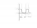
When I set the emitter resistor to give me a 70ma constant current then the voltage over the resitor looks something like this :
squarewaveshift.png

The duty cycle shifts from 50% to about 40% and the waveform is pretty deformed . I think it has more to do with transistor saturation than parasitic capacitances .
A slightly diffrent thing happens with the frequency but so as not to send you down a black alley i'm going to go down to the workshop and try it on a rigol oscilloscope and take a picture.
 

WBahn

Joined Mar 31, 2012
33,331
Ok say the input is a 50khz 50% duty cycle square wave .
When I set the emitter resistor to give me a 1 ma constant current then when I measure the voltage over the load resistor it gives me a nice 50% duty cycle square wave .

When I set the emitter resistor to give me a 70ma constant current then the voltage over the resitor looks something like this :

View attachment 60597

The duty cycle shifts from 50% to about 40% and the waveform is pretty deformed . I think it has more to do with transistor saturation than parasitic capacitances .
A slightly diffrent thing happens with the frequency but so as not to send you down a black alley i'm going to go down to the workshop and try it on a rigol oscilloscope and take a picture.
We need to see the actual circuit. What is the value of R. What is the input waveform. 50% duty cycle squarewave at 50kHz is not complete. What is the voltage. A "square wave" is a waveform that goes between +Vo and -Vo. Is that what you are using? Or are you just going between +Vo and 0V?

If you are placing the transistor in saturation, then you can't expect it to behave the way that it would if it were in the always in the linear region. Why? Because it's not in the linear region part of the time. There are junction capacitances that have to be charged and discharged as you go into/out of saturation and also as you go into/out of cutoff.. The data sheet will (should) describe these using various parameters such as recovery time and the like.
 

Thread Starter

Shagas

Joined May 13, 2013
804
My apologies I thought I mentioned this in my previous posts.

The circuit is the same as in the first picture with the two transistors (BC547B in this case).
The emitter resistor is 10ohm and there is a 10ohm resistor between the collector and VCC of the main transistor.
The input voltage is 0v to 5 v (Vcc) .

There are junction capacitances that have to be charged and discharged as you go into/out of saturation and also as you go into/out of cutoff.
Yes I guess that makes sense , I understand the problem abit more now.

Basically lets say I used an emitter resistor of 100 ohms , that would give me 0.7/100 = 7mA of current flowing through the emitter and 7mA - Ib (4.3/10k = 470uA) flowing through the collector so
considering that the bc547 has a typical Collector-emitter saturation voltage (from datasheet) of about 0.1V typ to 0.25max at IB = 500uA and IC = 10ma which are close to our calculated values 7ma and 470uA Ib then there is 5-0.7-0.1 = 4.2 to about 4 volts max that can be dropped over the load resistor before the transistor goes into saturation meaning that the load resistor has to be of value of 4.2/0.07 = 600ohms or less for the transistor to operate in the linear region .
Am I looking at this the right way?
 

Thread Starter

Shagas

Joined May 13, 2013
804
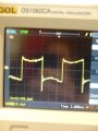
Also could anyone explain what these spikes are on the falling edges of the square wave?

DSC_0106.jpg

This is taken across the load resistor of 100ohm with 100ohm emitter resistor (setting Ic at about 7mA) @ 500khz 5v pk-pk input from a function generator.

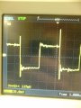
And this one at about 100khz :
DSC_0105.jpg
Why is it sagging inward at the highs and lows?

Thanks in advance for the inputs

Edit: this was done on a breadboard
 

WBahn

Joined Mar 31, 2012
33,331
My apologies I thought I mentioned this in my previous posts.

The circuit is the same as in the first picture with the two transistors (BC547B in this case).
The emitter resistor is 10ohm and there is a 10ohm resistor between the collector and VCC of the main transistor.
The input voltage is 0v to 5 v (Vcc) .
If you did I missed it. But it's taken care of now. Thanks.

Basically lets say I used an emitter resistor of 100 ohms , that would give me 0.7/100 = 7mA of current flowing through the emitter and 7mA - Ib (4.3/10k = 470uA) flowing through the collector
How are you getting an Ib of 470μA? Are you really saying that this transistor is operating with a β of only 15?

Where are you getting the 4.3V from?

Is all of the current flowing through the 10kΩ resistor flowing into the base of the transistor? Or is there, perhaps, some other path for it to follow?

so
considering that the bc547 has a typical Collector-emitter saturation voltage (from datasheet) of about 0.1V typ to 0.25max at IB = 500uA and IC = 10ma which are close to our calculated values 7ma and 470uA Ib then there is 5-0.7-0.1 = 4.2 to about 4 volts max that can be dropped over the load resistor before the transistor goes into saturation meaning that the load resistor has to be of value of 4.2/0.07 = 600ohms or less for the transistor to operate in the linear region .
Am I looking at this the right way?
You are more-or-less looking at it the right way. In order to keep the transistor in the active region, you want to stay well away from saturation. So don't define the edge of your operating envelop to be Vce of 0.1V, particularly when the spec sheet says that it can go to 0.25V. Instead, stay at Vce = 0.5V or even 1.0V or greater.

And please start tracking your units better. If I can do it, so can you.
 

Thread Starter

Shagas

Joined May 13, 2013
804
a β of only 15?
Yes it's strange .
The base current should actually be I=v/r since the base of the transistor is Vbe + 0.7(drop over emitter resistor) = 1.4 volts above the ground then
=> (5v-0.7v-0.7v)/10.000Ω should give an Ib of 3.6x10^-4 Amperes which is
360uA .

The emitter current is 0.7V/100Ω = 7mA
Collector current is 7mA - 0.360mA = 6.640mA
which gives a beta of 6.640/0.360 = 18.4 which means that I'm obviously missing something which I assume is the current flowing from the base into the regulating transistor.

It's 2am here , I will check up tomorrow , thank you for your input so far
 

WBahn

Joined Mar 31, 2012
33,331
Yes it's strange .
The base current should actually be I=v/r since the base of the transistor is Vbe + 0.7(drop over emitter resistor) = 1.4 volts above the ground then
=> (5v-0.7v-0.7v)/10.000Ω should give an Ib of 3.6x10^-4 Amperes which is
360uA .
But this is the current in the resistor. The resistor and the transistor base are NOT in series. So you can't just assume that the current in one flows into the other. Remember the whole point of the feedback transistor. It's there to shunt the excess base current away from the drive transistor's base. So you don't know what the base current is.

The emitter current is 0.7V/100Ω = 7mA
Collector current is 7mA - 0.360mA = 6.640mA
which gives a beta of 6.640/0.360 = 18.4 which means that I'm obviously missing something which I assume is the current flowing from the base into the regulating transistor.
Bingo.
 

WBahn

Joined Mar 31, 2012
33,331
Also could anyone explain what these spikes are on the falling edges of the square wave?

View attachment 60603

This is taken across the load resistor of 100ohm with 100ohm emitter resistor (setting Ic at about 7mA) @ 500khz 5v pk-pk input from a function generator.

And this one at about 100khz :
View attachment 60605
Why is it sagging inward at the highs and lows?

Thanks in advance for the inputs

Edit: this was done on a breadboard
First question that should always be asked -- are your probes properly compensated?

Being on a breadboard, you are going to have a lot of parasitic inductances and capacitances to wreak havoc on your measurements. As soon as you start taking good fractions of a megahertz, you are getting into the realm that you need to take good care in your breadboard layout. If you are dealing with a squarewave that is 100kHz, then your harmonics responsible for making sharp edges are well above 1MHz.
 

Thread Starter

Shagas

Joined May 13, 2013
804
Seems like i'll need to get a micro-ammeter so see what is flowing into the base .

***

Concerning the compensation , according to this video

http://www.youtube.com/watch?v=uOAzRlhrnYE

Maybe the probes are overcompensated because there were many probes in the workshop and I just picked one at random this time so that might have been the issue.

Thanks for the info
 

WBahn

Joined Mar 31, 2012
33,331
Seems like i'll need to get a micro-ammeter so see what is flowing into the base .

***

Concerning the compensation , according to this video

http://www.youtube.com/watch?v=uOAzRlhrnYE

Maybe the probes are overcompensated because there were many probes in the workshop and I just picked one at random this time so that might have been the issue.

Thanks for the info
Whenever you use probes, always compensate them unless you are making extremely rough measurements and just want a very rough representation of the general waveform. And remember that when you compensate a probe, you are matching it to that particular channel of that particular scope on that particular day (though the latter doesn't change that fast). If you move it to a different channel on the same scope, you need to recompensate it.

In general, you can't just grab probes that are meant for scope X and expect to be able to use them on scope Y. A given probe has a limited amount of compensation adjustment intended to match a certain range of channel input capacitance.
 
Top