Facebook
 Google
 GitHub
 Linkedin
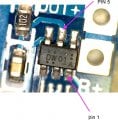
Hi guys i have had found an issue with ALL board purchased on the latest batch ( 100 units ) of tp4056 protection , from ebay , aliexpress
It appear that the 100R( R5) resistor and the 1K0 (R6) have been swapped on the pcb on the these style of boards, and from what i can see will not function correctly
This appears to be a common fault looking at any google picture on the web for this design PCB
Also attached is the circuit and another pcb layout which has the components correctly mounted

Not sure if others have found this prior , but simple search of web did not show it
Please comment and check your boards if you have this design
Cheers


It appear that the 100R( R5) resistor and the 1K0 (R6) have been swapped on the pcb on the these style of boards, and from what i can see will not function correctly
This appears to be a common fault looking at any google picture on the web for this design PCB
Also attached is the circuit and another pcb layout which has the components correctly mounted
Not sure if others have found this prior , but simple search of web did not show it
Please comment and check your boards if you have this design
Cheers
Last edited by a moderator: