Topo Map with flashing LED

Bernard

Joined Aug 7, 2008
5,784
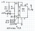
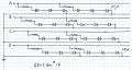
View attachment 106439 View attachment 106439 Re post 36, traveling blanks with groups of 4 LED's in series. Just one section of LED's breadboarded, 16 LED's, really just 14, ran out of room. 600 uA still quite bright & if allowing 15 mA sinking current ( bring to ground ) then looks like 400 LED's would be possible from a 4022, little brother to 4017.
4 in series does look better than 3 in series.
Stream # 15 00000.jpg
The video made it as far as youtube, Stream, 4 bit, but can not seem to make it to AAC
Live looks better than the short video, conflict of frame rate vs 555 clock ??
 
Last edited:

Bernard

Joined Aug 7, 2008
5,784
Nice video, looks like 2nd stage is not triggering 3rd stage. Momentarily ground pin 2 of U 3 to see if it will trigger. Is pin 4 connected to R 7 ? Check all wiring around U 3.
 

Thread Starter

lednoob

Joined Jan 13, 2016
171
Nice video, looks like 2nd stage is not triggering 3rd stage. Momentarily ground pin 2 of U 3 to see if it will trigger. Is pin 4 connected to R 7 ? Check all wiring around U 3.
im still troubleshooting. also, Will the led's always be on? i would like to have this circuit continuously run without pushing the button. all led's are off the pushing the main button starts the circuit. I love this sequence instead of the chase.
 

Bernard

Joined Aug 7, 2008
5,784
We can convert start SW to start on power-up, & can also change from circulating dark LED's , to circulating
lit LED's, all other LED's off. Would be helpful to know what LED is proposed for this circuit, Vf, operating current & color.
 

Thread Starter

lednoob

Joined Jan 13, 2016
171
We can convert start SW to start on power-up, & can also change from circulating dark LED's , to circulating
lit LED's, all other LED's off. Would be helpful to know what LED is proposed for this circuit, Vf, operating current & color.
I like to do the power up switch idea and the if we can do the continuous circulating. How do I change the speed? I want to use the Color blue or green for this circuit. I don't have the led's yet. I was using these red led's because I have like a thousand of these so I use it for testing.
 

Thread Starter

lednoob

Joined Jan 13, 2016
171
Time enough to post modification to Stream # 14, in Stream #14 A with power-up start. & Stream #15 rearrangement of LEDs for all off except one of 3 circulating
so do i do this modification for all 3 555's? Do I add a 4th since you have 4 channels? Also the stream #15 says #16 on the circuit. I believe you mean #15 unless I am missing one. I also just want to say thank you for sticking with me and having patients. You have been a great mentor!
 

Thread Starter

lednoob

Joined Jan 13, 2016
171
so do i do this modification for all 3 555's? Do I add a 4th since you have 4 channels? Also the stream #15 says #16 on the circuit. I believe you mean #15 unless I am missing one. I also just want to say thank you for sticking with me and having patients. You have been a great mentor!

Is it supposed to look like this?
 

Attachments

Bernard

Joined Aug 7, 2008
5,784
Stream # 14 A only effects input to U1; U2, U3 no change except R8 is gone. C 7 holds pins 4 low for about 10 msec., so C 10 must hold U 1-2 low
longer than 10 msec.
When first breadboarded, Stream #15 LED's were connected in groups of 3 & seemed to be a little bit choppy so reconnected as groups of 4 which I think looks better, dealer's choice. If going to groups of 4 with Stream # 14, then would need to add another 555, but with Stream # 15, just move reset up one stage, old stage becomes latest output, ( D ). If using green LED's, Vf about 2.5 V, @ 5 mA, then 3 in series would be about right, making R's about 700 ohms. With 555 as LED drivers, & 5 mA is satisfactory, current drain only about 45 mA/ 100 LED's / one series parallel string for total of 400 LED's; If using 4022 or 4017 LED drivers will be needed, 4 2N2222's. The 4022 would be my choice.
Stream #16, One on, 3 off, 4 stages for use with either 555's or 4022, 4017. The LED's are spread out for
ease od drawing, but are wired as a single line.
 

Thread Starter

lednoob

Joined Jan 13, 2016
171
Stream # 14 A only effects input to U1; U2, U3 no change except R8 is gone. C 7 holds pins 4 low for about 10 msec., so C 10 must hold U 1-2 low
longer than 10 msec.
When first breadboarded, Stream #15 LED's were connected in groups of 3 & seemed to be a little bit choppy so reconnected as groups of 4 which I think looks better, dealer's choice. If going to groups of 4 with Stream # 14, then would need to add another 555, but with Stream # 15, just move reset up one stage, old stage becomes latest output, ( D ). If using green LED's, Vf about 2.5 V, @ 5 mA, then 3 in series would be about right, making R's about 700 ohms. With 555 as LED drivers, & 5 mA is satisfactory, current drain only about 45 mA/ 100 LED's / one series parallel string for total of 400 LED's; If using 4022 or 4017 LED drivers will be needed, 4 2N2222's. The 4022 would be my choice.
Stream #16, One on, 3 off, 4 stages for use with either 555's or 4022, 4017. The LED's are spread out for
ease od drawing, but are wired as a single line.
 

Bernard

Joined Aug 7, 2008
5,784
The 2N222 is upside down, should be connected as an emitter follower, collector to + 12 V, emitter to R's. LED's in parallel is not a good practice, better to put 4 red LED's in series. R would then be about 600 ohms @ 5 mA. Peak dissipation in 2N2222 about 1 W so might run a bit hot. Gain may fall off at peak current so timing circuit may be over loaded. Suggestion-- start over., re check some of Wendy's circuits.
What LED's are planned? & how bright ? Might measure Vf on a few at different currents. Consider PWM.
 

Thread Starter

lednoob

Joined Jan 13, 2016
171
The 2N222 is upside down, should be connected as an emitter follower, collector to + 12 V, emitter to R's. LED's in parallel is not a good practice, better to put 4 red LED's in series. R would then be about 600 ohms @ 5 mA. Peak dissipation in 2N2222 about 1 W so might run a bit hot. Gain may fall off at peak current so timing circuit may be over loaded. Suggestion-- start over., re check some of Wendy's circuits.
What LED's are planned? & how bright ? Might measure Vf on a few at different currents. Consider PWM.

ok, not sure where to start on pwm circuit.
 

Thread Starter

lednoob

Joined Jan 13, 2016
171
No better. I have one on breadboard that looks promising. Need to know what LED's to use.

I have like 500 super bright red diffused LED's but I don't have any specs. I am assuming it's the standard 30ma but don't know the triggering voltage. I have so many so I want to use them up.
 

Thread Starter

lednoob

Joined Jan 13, 2016
171
I have like 500 super bright red diffused LED's but I don't have any specs. I am assuming it's the standard 30ma but don't know the triggering voltage. I have so many so I want to use them up.

Hi Bernard, so I don't have a stream #15. I have #14, 14A and 16. I like your suggestion of using Stream #15 and not using another 555 timer. can you supply me Stream #15?

Thanks,
Steve
 
Top