Topo Map with flashing LED

Thread Starter

lednoob

Joined Jan 13, 2016
171
? Post # 159 = yes.
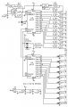
On Stream #2, C1, 555-2 is .2 uF. Either 74LS164 or 74HC164 will work but as the LS has poor high output
it was wired as low side output with a disadvantage of if the Clear is low, all LED's would be on. Not a problem
if Wendy's timer-power control were used. The 74HC164 has = output drive high or low so Stream #3 is configured for high output V, making Clear available for logic disable.View attachment 100344

Wow, how is it that both of you know so much about electronics? Are both of you like professors? I'm such a beginner so I am happy to learn from both of you. My background is commercial photography, welding, powder coating and cooking. Especially BBQ! I just love building stuff. I want to strengthen my electronics because that was my Dad's background and chemistry. Thanks for taking the time to help me out.
 

Wendy

Joined Mar 24, 2008
23,415
I started playing with circuits before I was a teen, I'm 59 years old now. You might say I have learned a few things.

I figure the CMOS power switch will power all your other circuits, it is how I interpreted what you asked for. Basically it is a power switch, and a timer.

You have to understand my ExpressPCB schematics/layouts are working versions. My final print is based on them but not dependent on them. Having said that, here you go.

The important print the the hand touched one, the file 100.gif . I print it out using Gimp at 600 DPI and use it to make my PCB boards.
 

Attachments

Bernard

Joined Aug 7, 2008
5,784
I started while on my way home from PS 14, NYC, 1937 ?, by going thru a radio repair shop's trash & came up with parts for a crystal radio. More bits & pieces along the way to here I am at 89 years old.
Thought it might be helpful to show power up - manual reset for Stream. B circuit. When power is applied a + V is applied to the NOR gates via a 20 uF & 10k R. With a momentary low on each 555 pin 4 reset, all pin 3's go low, resetting all circuits. The B circuit requires 3 low reset signals, blinking LED, 555 clock, & clear bus line which the 555 B provides. For C circuit, the 555 C output might connect to the gate of the FET. A circuit still to be determined.Lock out #2 00001.jpg Lock out #3 00000.jpg
 

Thread Starter

lednoob

Joined Jan 13, 2016
171
I started while on my way home from PS 14, NYC, 1937 ?, by going thru a radio repair shop's trash & came up with parts for a crystal radio. More bits & pieces along the way to here I am at 89 years old.
Thought it might be helpful to show power up - manual reset for Stream. B circuit. When power is applied a + V is applied to the NOR gates via a 20 uF & 10k R. With a momentary low on each 555 pin 4 reset, all pin 3's go low, resetting all circuits. The B circuit requires 3 low reset signals, blinking LED, 555 clock, & clear bus line which the 555 B provides. For C circuit, the 555 C output might connect to the gate of the FET. A circuit still to be determined.View attachment 100395 View attachment 100396

Wow! I have so much respect for both of you. I'm almost 50 and I feel like i have barely scratched the surface of electronics. Digging thru my Dads stuff, I have found all sorts of stuff. My Dad has been called a pack rat but as he stated, He is a collector of vintage parts that sill has use. I guess the saying is true. "One Man's Junk in Another Man's Treasure". I found some Transistors and regulators that are T-03 package and I guess they don't make them any more? I have a bunch of heat sinks that go with them. I also have a 110v solenoid coil that was used to magnetize screwdrivers. That is pretty cool in my books. Anyway, thanks for all the help and I am studying your schematic.
 

Thread Starter

lednoob

Joined Jan 13, 2016
171
Hi Wendy & Bernard. I am back on my feet and plan to make some boards. I have been out from a car accident and finally able to work on stuff. I will upload a final schematic and would like to have you proof read it since both of you have the Veteran eyes. Thanks for your help.

Steve
 

Bernard

Joined Aug 7, 2008
5,784
Welcome back; wish it were under better circumstances like a trip to Big Bear.
Re: Stream using shift registers, other inputs could be used other than blinking candle ( which I still like )
such as circulating a single bit like the 256 bit matrix. On drawing, at reset, RE, the RS latch is set putting a 1 on data input. On next clock the first LED lights & latch is reset. When the 1 advances to the last SR stage it re inserts a 1 to the first stage. It still needs to be made compatible with 15 sec time out ckt.STREAM #4 00000.jpg
 

Bernard

Joined Aug 7, 2008
5,784
If Stream #3, post #160, were configured as in post # 167, to a single circulating bit ( or several ),
then a tail can be added per post #142 & Stream #5. Tail will be about 5 LED's long.
Best results seem to be 6 mA for brightest LED, total drain on one pin of 74HC164 is about 15 mA.
IC V out_ I mA_ LED V
5.96----- 1
5.87----- 4---- 2.84
5.80----- 6---- 2.9
5.73----- 8---- 2.99
5.67----- 10---- 3.06
5.45 ----- 15-- still qualifies as a logic 1.STREAM #5 00000.jpg
 
Last edited:

Thread Starter

lednoob

Joined Jan 13, 2016
171
If Stream #3, post #160, were configured as in post # 167, to a single circulating bit ( or several ),
then a tail can be added per post #142 & Stream #5. Tail will be about 5 LED's long.
Best results seem to be 6 mA for brightest LED, total drain on one pin of 74HC164 is about 15 mA.
IC V out_ I mA_ LED V
5.96----- 1
5.87----- 4---- 2.84
5.80----- 6---- 2.9
5.73----- 8---- 2.99
5.67----- 10---- 3.06
5.45 ----- 15-- still qualifies as a logic 1.View attachment 102307


Hi Bernard, I am going to gather all the posts and assemble them like a puzzle and will ask for you to proof read it if you are available. Thanks for the help. I have been out for physical therapy and pain meds and I am starting to get my strength back to do some work. I'll keep you posted.
 

Bernard

Joined Aug 7, 2008
5,784
Glad that you are back. We'll be here.
50 aquablue LEDs on sale for $ 5, just could not resist. Real pretty. Might make a short river.
 

Bernard

Joined Aug 7, 2008
5,784
Might take a look at, 81 LED Chaser, & LED Chaser With a Twist 32 LED pattern cycle, on
You Tube, click FORUM top of page, scroll all the way down, click You Tube.
 

Thread Starter

lednoob

Joined Jan 13, 2016
171
Hi Wendy I have been working on making your 100 LED seq board and I was wondering which NPN are you using or what do you prefer? Ref Q1 - Q20.

I am gonna make the board that you gave me and eventually add other suggestions that you and Bernard have mentioned. I have been away but now I have a little time to play with the circuits.


Thanks all for your help!
 

Bernard

Joined Aug 7, 2008
5,784
2N2222, 2N3904 or other NPN's similar.
In post # 38 of Pseudo- Random multiple LED's - - - , takao21203 makes a parts supplier recommendation for G&C. Might be one stop shopping.
Re post # 168: A single LED moving in a string leaves a reasonable tail from eye persistence so maybe we can drop diodes ?
 
Last edited:

Thread Starter

lednoob

Joined Jan 13, 2016
171
2N2222, 2N3904 or other NPN's similar.
In post # 38 of Pseudo- Random multiple LED's - - - , takao21203 makes a parts supplier recommendation for G&C. Might be one stop shopping.
Re post # 168: A single LED moving in a string leaves a reasonable tail from eye persistence so maybe we can drop diodes ?

Hi Bernard, when i was looking at Wendy's circuit, Q11 - Q20 looks like a CMOS transistor with drain, gate & source. Could I use a regular 2N2222 or can you recommend a CMOS?
 

Attachments

Thread Starter

lednoob

Joined Jan 13, 2016
171
A power on monostable (the MOSFET is not critical)...

View attachment 100203

Minor revision on 16 output controller (look at the power up reset)...

View attachment 100202

A power on monostable (the MOSFET is not critical)...

View attachment 100203

Minor revision on 16 output controller (look at the power up reset)...

View attachment 100202

Hi Bernard, it seems that Wendy is unavailable at this time so maybe you can help me. on Post #149 can you review it and let me know if the vcc supplied to the chasing circuit 4017 and 555 is normally off then turned on by pushing a switch that is triggered to a 555 with an FET as the output which then supplies power to the chasing circuit of the 555 and 4017 indicated by Wendy's schematic?. My guess is that the push button switch triggers timed power that supplies vcc to the chasing circuit then off when time is up. like a darkroom timer. Sorry for the confusion. I'm trying to understand how it works.

Thanks
 

Wendy

Joined Mar 24, 2008
23,415
Been kinda occupied with life. What is the question? I think Bernard covered it. You will need base resistors for a NPN transistor like a 2N2222 (AKA PN2222).
 

Thread Starter

lednoob

Joined Jan 13, 2016
171
Been kinda occupied with life. What is the question? I think Bernard covered it. You will need base resistors for a NPN transistor like a 2N2222 (AKA PN2222).


Nice to see you back Wendy and thanks for taking time out of your busy life. I was trying to do the schematic post #149 circuit for 256 LED's. I see the separate circuit with the push button activation. Question is, The push button circuit will supply 12v vcc to the chasing circuit of the 4017's and 555 timer? Also you have a LM317 tied to the 2nd section of transistors. Is the LM317 dedicated to only these transistors? If so, can I use a 7812 fixed reg for the rest of the vcc triggered by the push button?

Thanks for your help
 
Top